The next 2 days were spent assembling the suspension and then putting the engine and gearbox into the car.
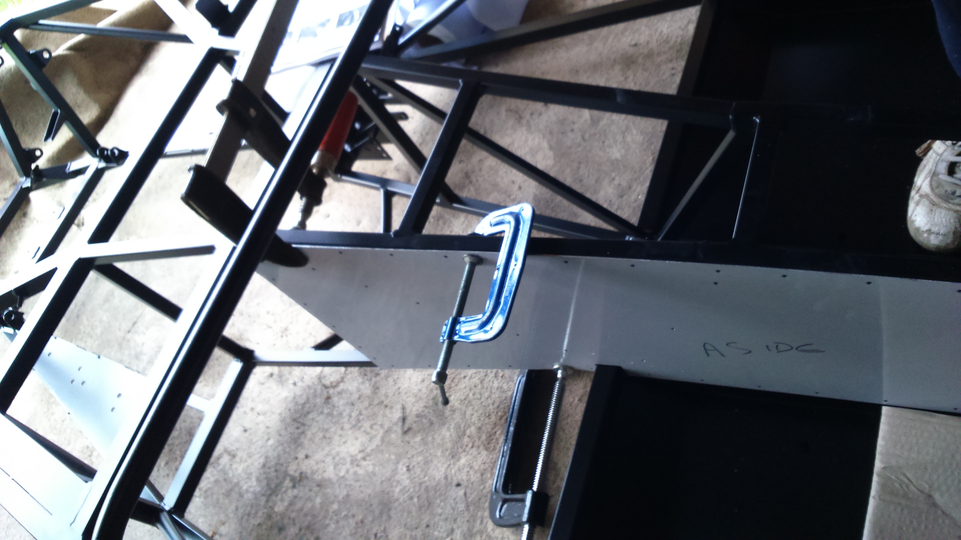
The chassis was put flat onto the ground and then lifted onto axle stands so that I could fit the suspension. We inserted the bushings at a local garage who let us borrow their press so thanks to Wayne at Greenfields Service Station. These were assembled to the chassis using the supplied bolts.
The diff had to go in before the rear uprights/driveshafts and this was not so straightforward. There is a reduction sleeve that has to go through the diff, unfortunately there are already 2 other sleeves in the hole! These sleeves were forced out and the Westfield sleeve was pressed in.
After lifting the diff into the chassis and trying to bolt in place, we found that the lower diff bracket clashed with the chassis and would not allow it to move into place. The diff therefore came out and I used a grinder and file to take away part of the bracket. The diff then went in and was bolted in place.
The rear uprights were next along with the rear shocks and were fairly straightforward. Westfield had advised shocks with rose joints rather than bushes as the rear shocks are at a bit of an angle, so I ordered a set of Protech Shocks with rose joints and they supplied the relevant spacers to fit this.
The front uprights went on easily although one of the upper ball joints was stiff into the wishbone. The instructions say this is an M18 thread but it is actually M14 so an M14 tap will be needed to clean this thread.
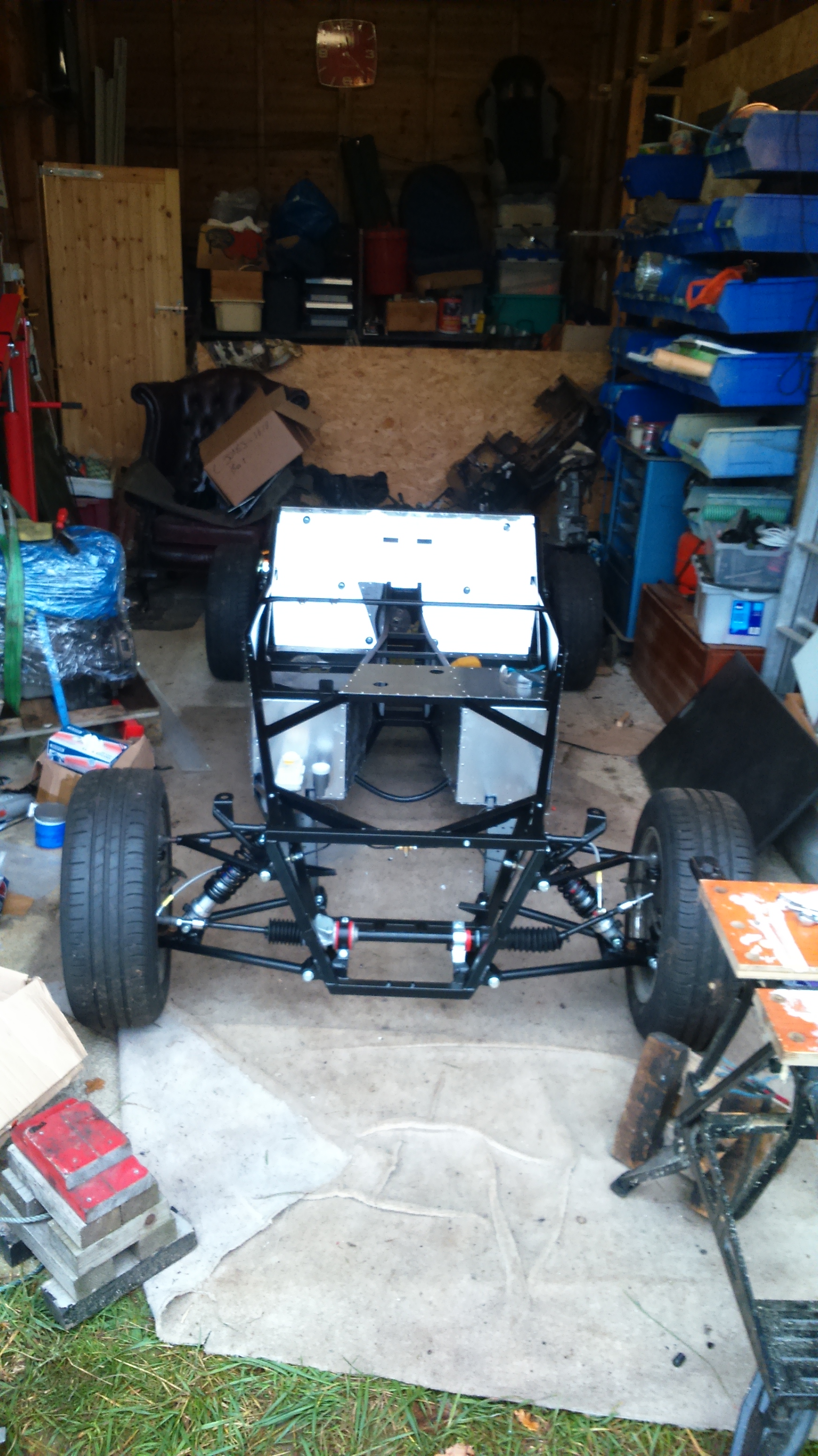
The steering rack was then fitted using the supplied mounts. We found a problem at this stage as one of the track rod ends did not fit onto the rack extensions and would literally just fall off. After a few phone calls with Westfield, they advised that they don’t do track rod ends for the Mazda so I needed to return them and use the standard track rod ends. If I knew that, I wouldn’t have removed them from the uprights with force and therefore destroy the dust boots. Better order some more…
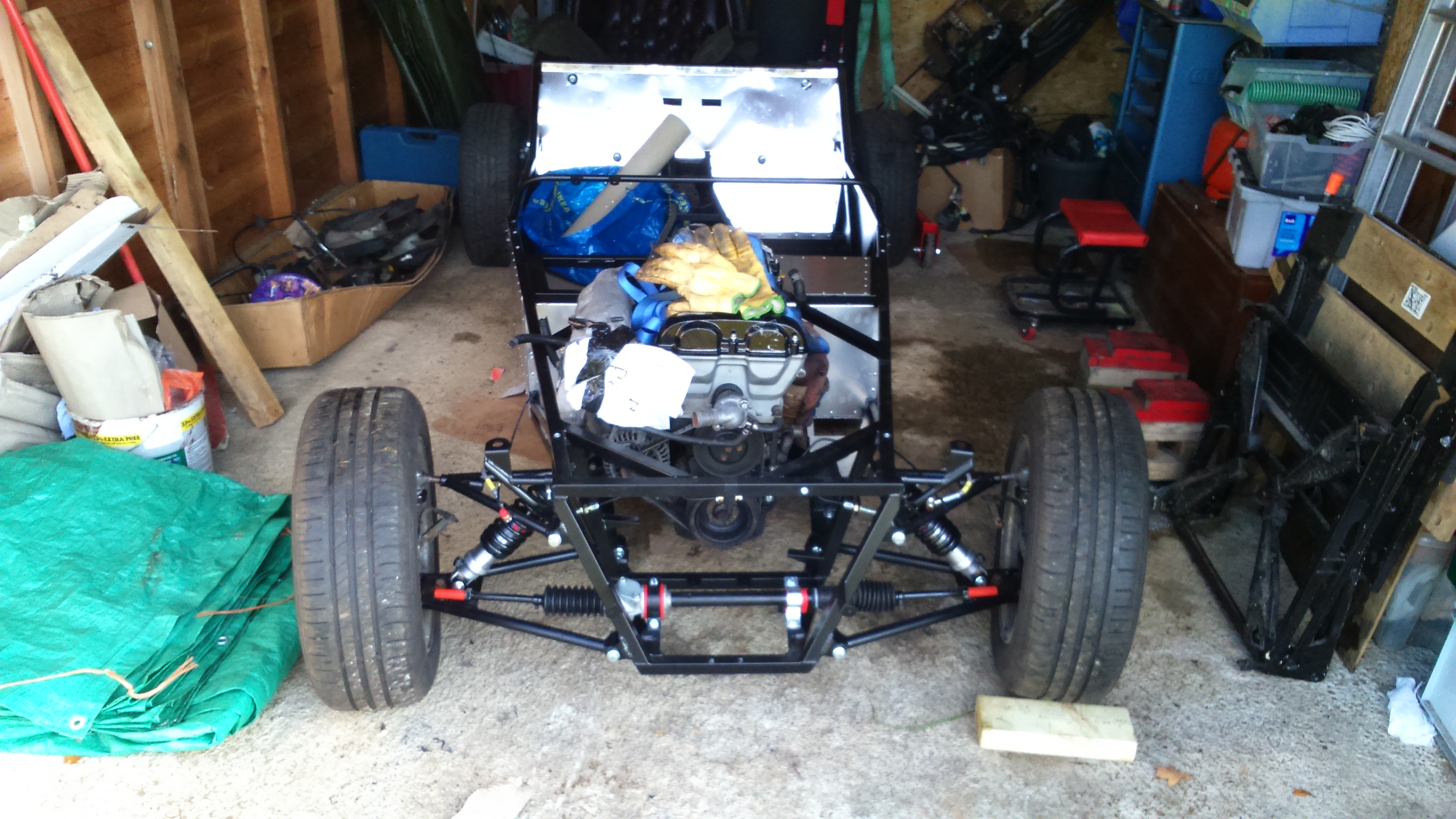
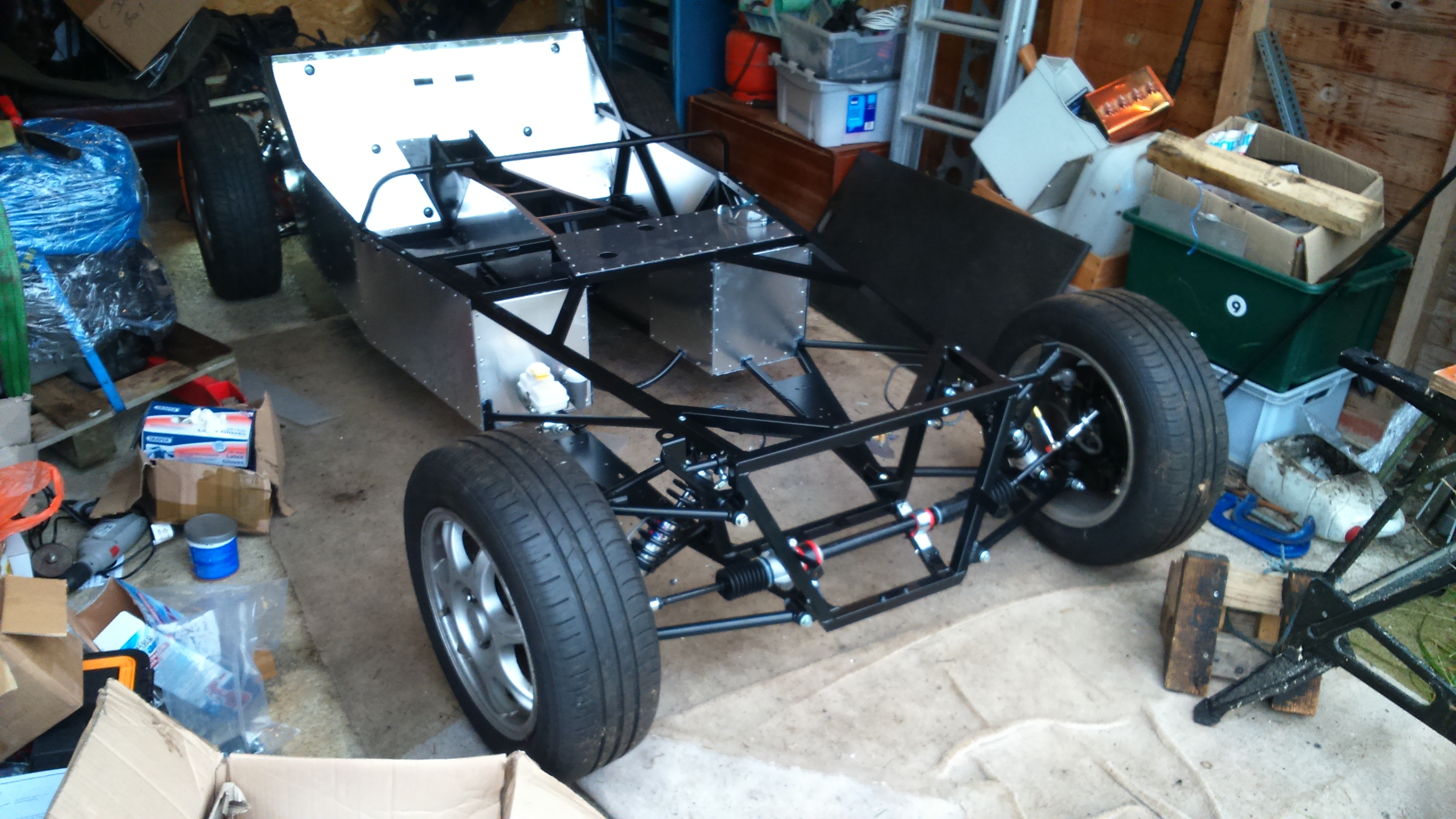
The wheels were then fitted and the car was lifted off the axle stands. This felt like a big milestone and quite an achievement!
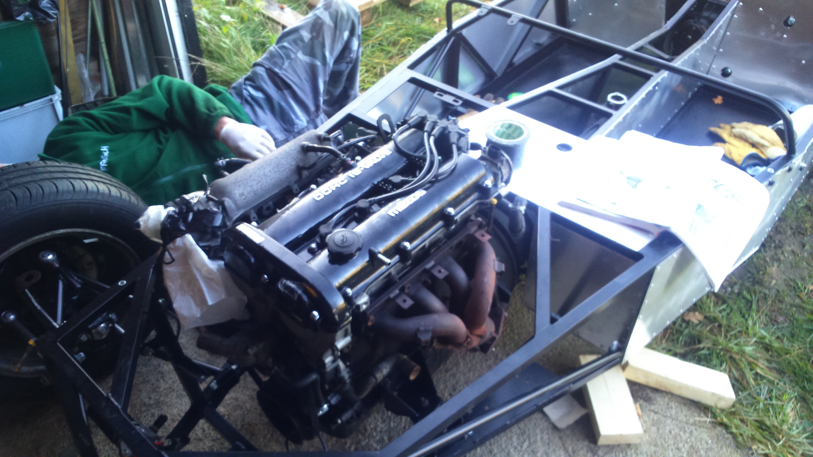
On my final day in Norfolk, we reattached the gearbox to the engine, attached the various Westfield mounts and then went to attach the rubber engine and gearbox mounts which we did not have… A phone call to Westfield and it turns out we were meant to order these separately. My Dad managed to source engine and gearbox mounts to use. The engine mounts are from a Ford and look exactly the same as the Westfield one although not sure how stiff they are in comparison.
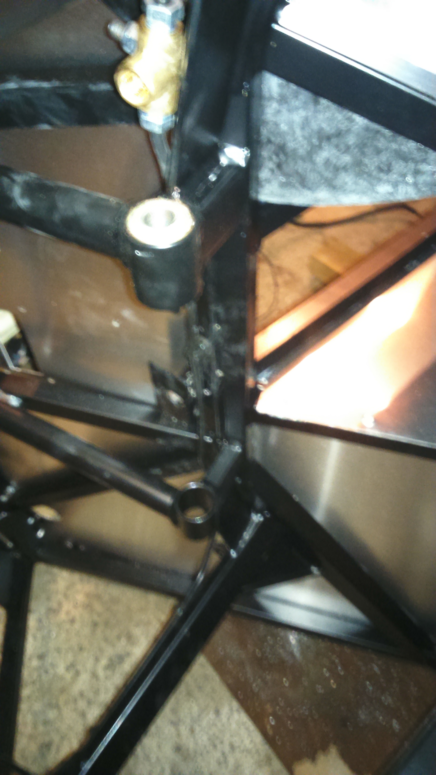
We then inserted the engine and gearbox into the chassis and found that the engine mounts were a long way off lining up with the holes in the chassis. We played around with this for a while but there was no way it was going to fit and even if it had done, the engine would have been at a very extreme angle in the chassis. We therefore fitted the right hand engine mount and re-drilled the holes for the left hand mount. This way round gave enough clearance for the clutch slave cylinder to operate but using the standard holes on the left did not. Once in place, we marked the gearbox mounts, lifted the engine out and drilled the gearbox mounts before refitting.
If the mounts and holes had all lined up then the whole engine fitting could have been done in 30 mins, the large engine bay made this quite easy.