On the first day of the Christmas holiday, I wanted to get a few odd jobs done before moving on to the wiring.
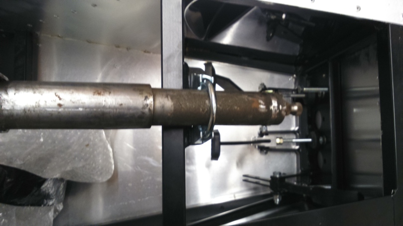
First was the upper steering column which needs to have this bracket cut off with an angle grinder.
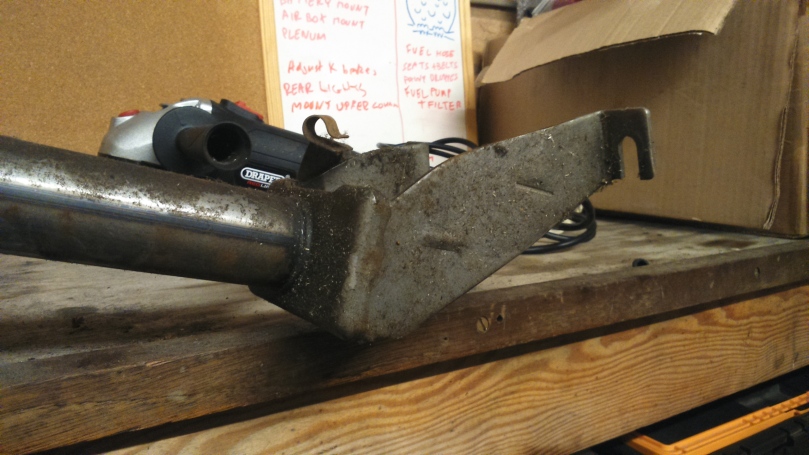
Once cut off, the column could then be fitted to the car. (The U clamp is too big in this photo but is now correct)
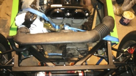
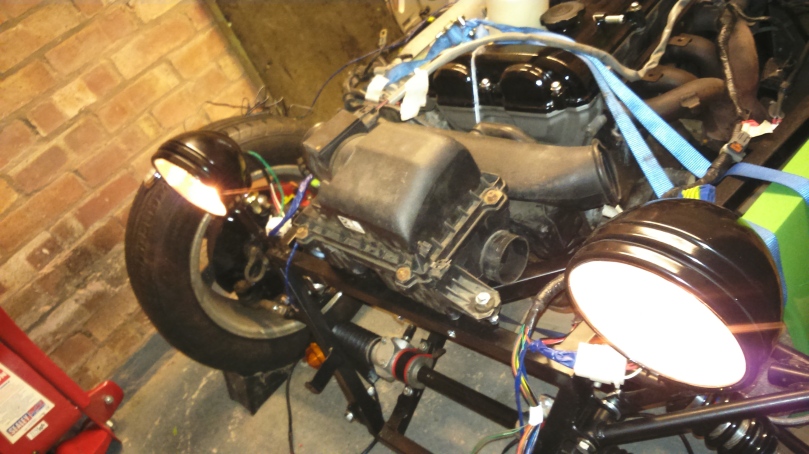
Next I fitted the fuel hoses between the pipes and the fuel rail and then the intake plenum.
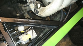
I’m not sure if I got the wrong bolts in my kit or used the wrong ones elsewhere but the rear upper wishbone bolts were not long enough so I replaced these with new ones and torqued up all bolts in the suspension.
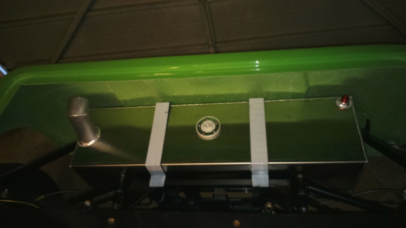
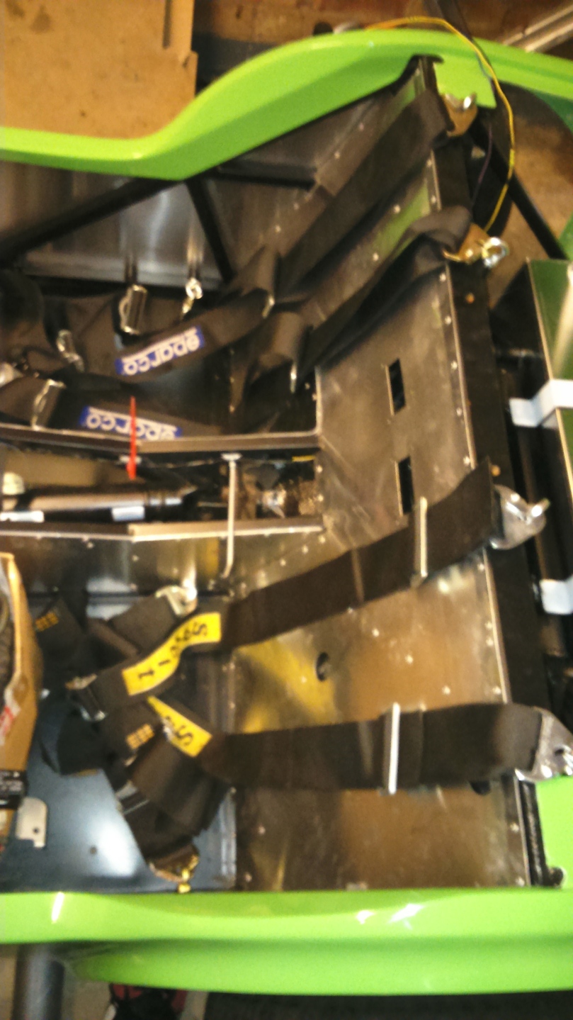
I then put the fuel tank in place with foam padding around the straps and chassis surface.
Next were the harnesses which were a donation that had been used for racing but were now out of date (Thanks Tom!). They will need adjusting but I will get the seats and crutch belts in first.
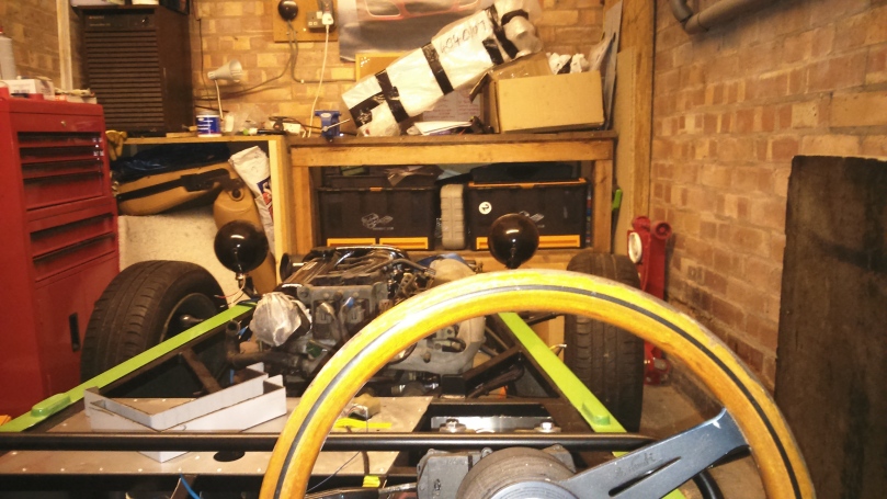
Then it was time to sit in and pretend to have a drive! When sitting on the floor I actually look through the steering wheel rather than over it.
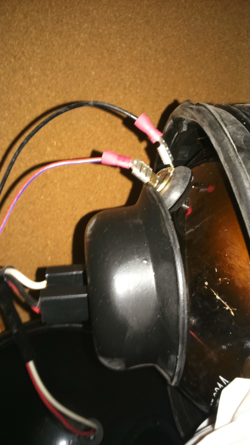
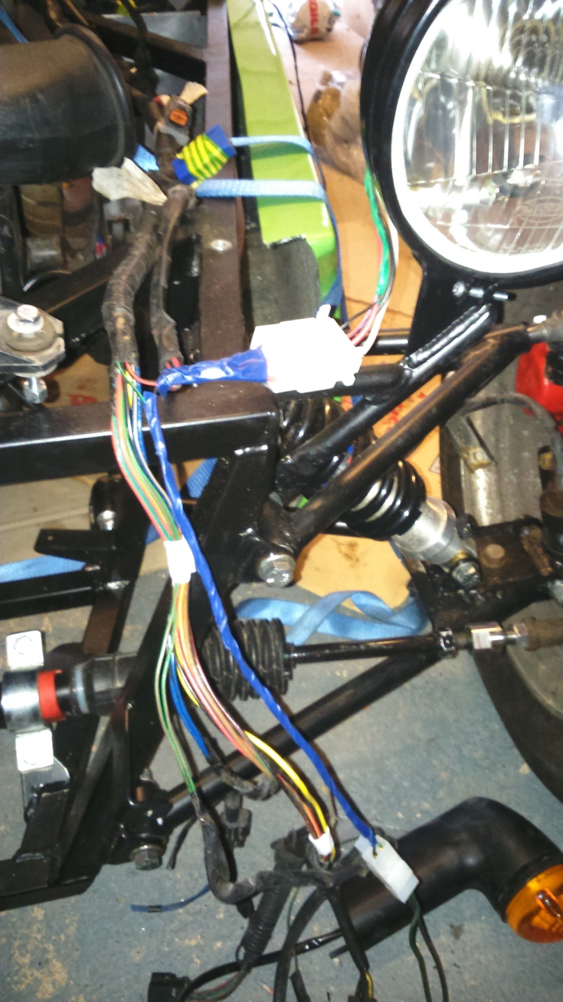
Now it was time for the wiring. I started with the lights in the hope I could get at least something working by the end of the Christmas holiday. The headlight units have 4 wires attached (dipped beam and main beam) but nothing for the sidelights.
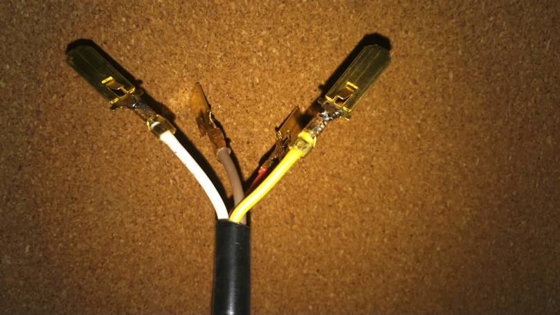
I had bought a load of connectors for the lights and crimped and soldered the terminals on.
After struggling to open the lights up, the side light connections were obvious and had no wires attached at all so I attached my own with crimps.
I then laid out the wiring harness from the MX5 and attached what I could.
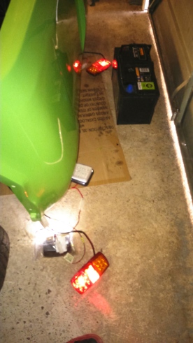
 I repeated a similar process for the rear lights too, using the wiring that I had previously attached.
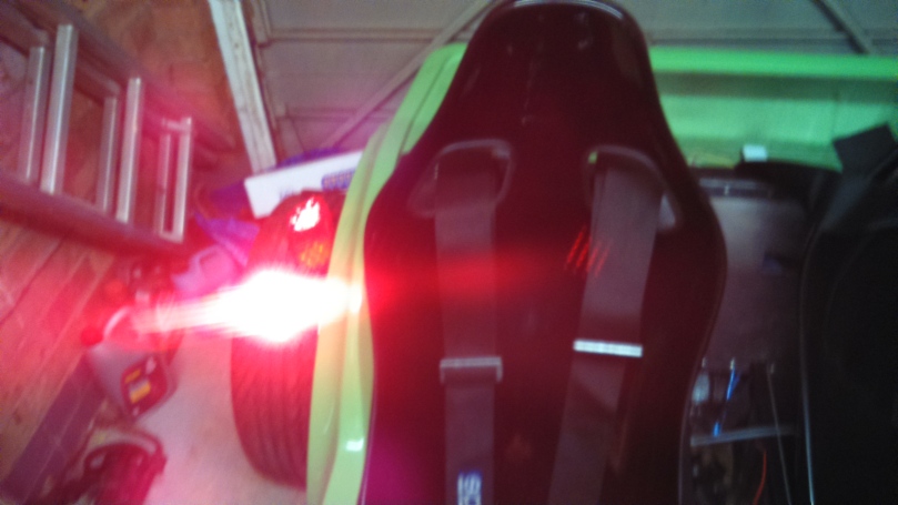
I then connected a battery to test the lights and IT WORKS! Well, the sidelights, dipped beams, full beams and number plate light worked. There is virtually no circuit for the fog light yet (as my car was an Eunos and the added circuit was removed). The reverse light worked but the wiring didn’t reach the gearbox wiring. The indicators flashed but very quickly indicating an error and the hazard lights didn’t work as I left the switch and wiring in Norfolk…
From some research, it turned out that the indicators were flashing too fast as I have used LED indicators for the rear and side repeaters. The flasher unit therefore doesn’t see enough current and thinks there is a problem.
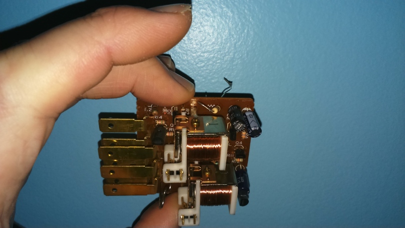
From further research, I initially found 2 solutions; Add some big resistors to each circuit to draw more power (this seems a bit of a bodge and the resistors will get hot if used much), or get a different flasher unit. The flasher units have either 3 or 4 terminals so I checked how many mine had which turned out to the 7…
So I carried on my research and found an American Miata forum where they modified the Mazda flasher unit to achieve the desired result by replacing resistor R1 in the RC circuit. At the top of the photo below is the resistor I changed to a 1 mega ohm 1/4W resistor. This isn’t in very neatly as the heat damaged the bottom of the board slightly so I stopped (the connection is fine)
http://forum.miata.net/vb/showthread.php?t=335534
With this back in the car, the indicators flashed perfectly and it cost me nothing!
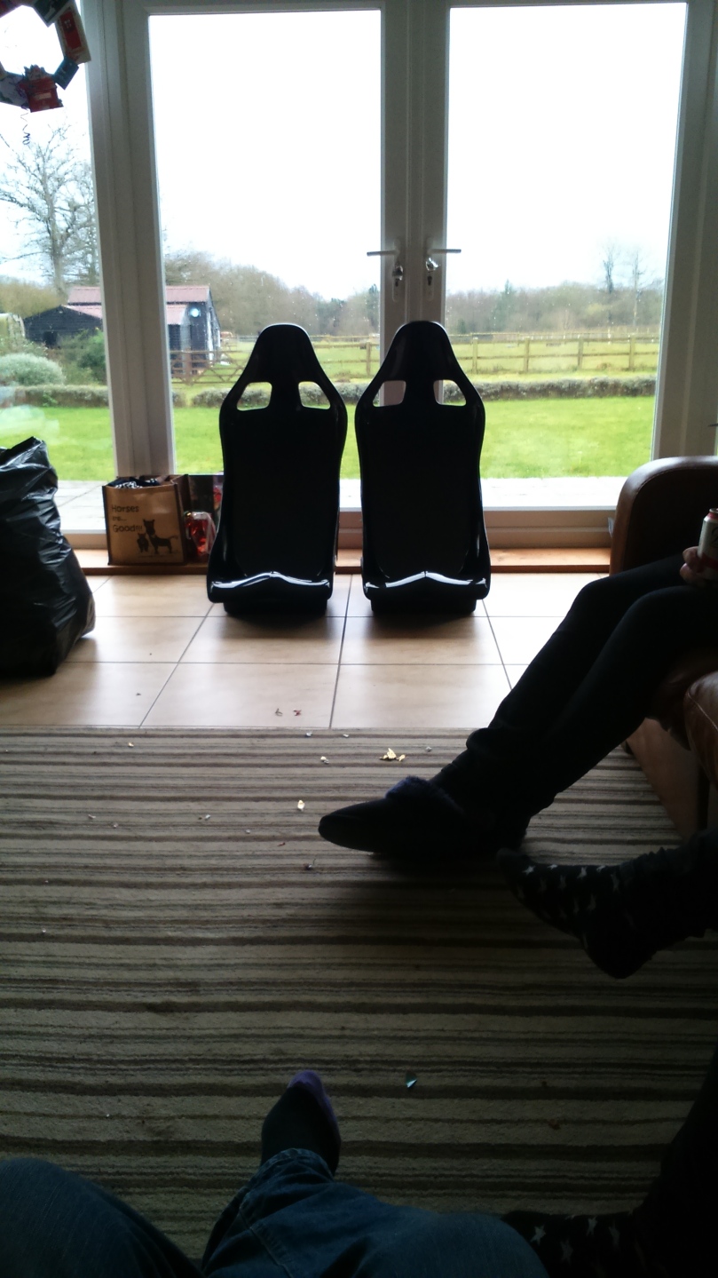
Then I spent a few days away for Christmas and progress stopped but I did get some seats from my parents (Birthday and Christmas present). These are made by JK Composites out of GRP and weigh about 4.5kg each with the base.
The version I went for is N3946 as this is the widest that will fit in the passenger side of my car. These are about the right size for me but there may be limitations on who can have a lift!
I’m very impressed with these seats so far and are surprisingly comfortable without any padding.
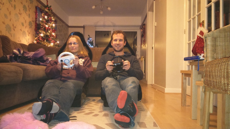
They are also great for playing Mario Kart…
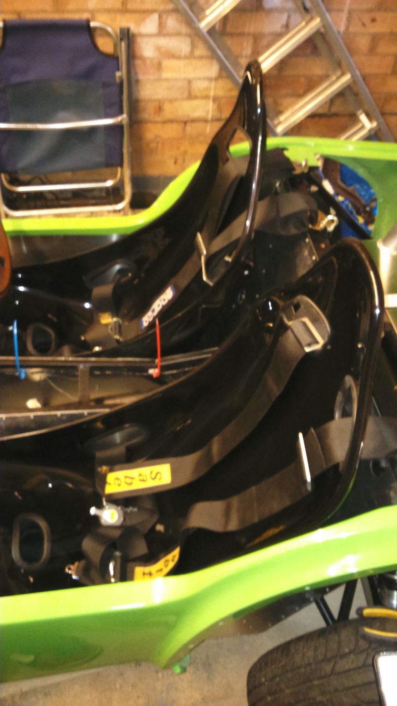
And then placed in the car. I need to either get some tracks or drill further holes in the chassis to mount them properly. For now they are held in with 2 screws so I can sit in without them moving.
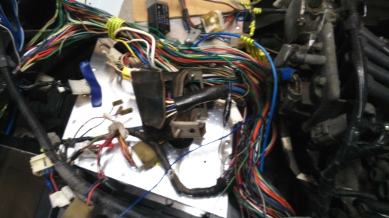
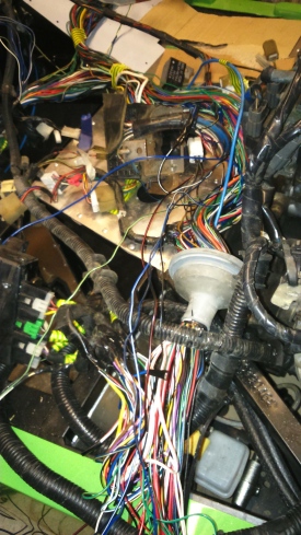
Next was to remove the wiring that isn’t needed and save some weight. This is a very slow process as I won’t be needing electric mirrors, electric windows, heated rear screen, audio…
There were also a lot of wires that needed either lengthening or shortening so this took up even more time.
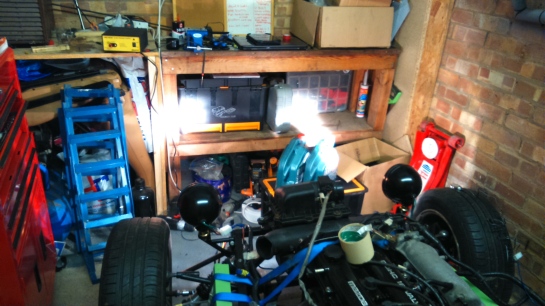
There were times that I wondered what I had done and if it would ever work again:
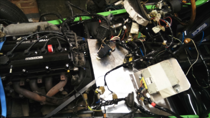
I then tested that everything still work and even tried the starter which successfully turned the engine over!
Once mostly sorted out, I started insulating the wires. I will be replacing the speedo which may result in more simplification.
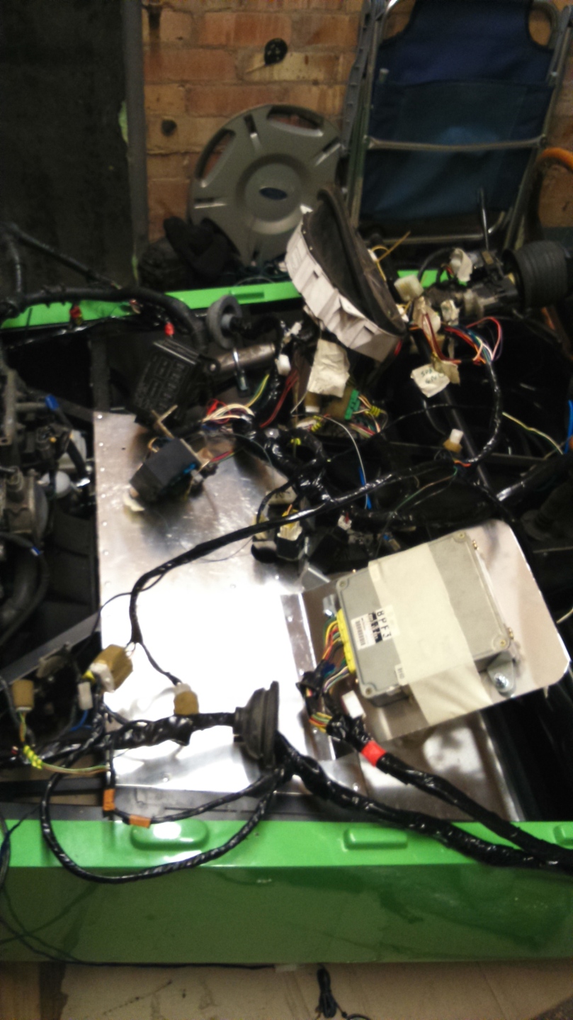
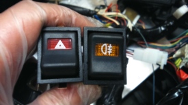
Once the wiring was relatively tidy, I sorted out the switches for the hazard lights and fog light, plus the relay needed for the fog light (it can only come on when the lights are on and when ignition is on.). I therefore have side light power running through the switch which controls the relay and then power through the relay which goes to the fog light. The source I found for this was the electric window fuse as I probably won’t be needing that anymore.
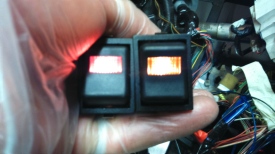
The blurry images below show that my circuits worked and the switches are lit when the side lights are on.