The First Drive (and lots of smoke)

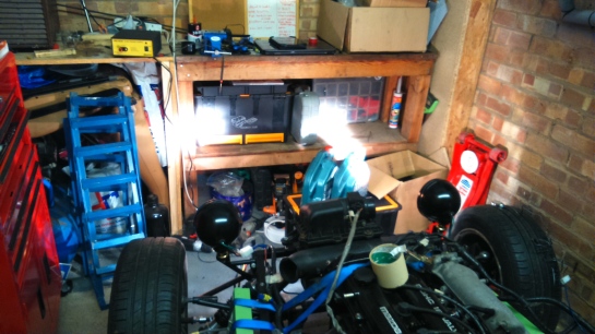
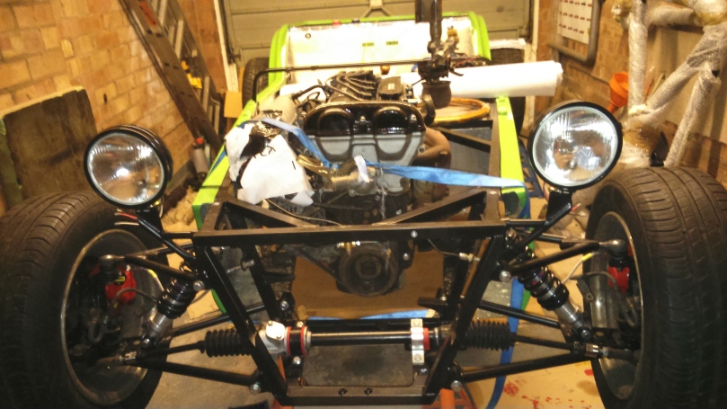
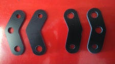
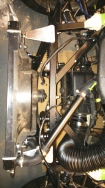
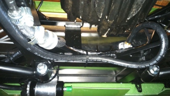
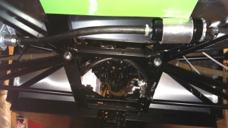
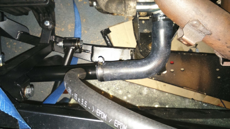
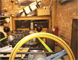
Got my radiator mounts made by http://www.oreracing.co.uk/ and fitted them to hold everything together properly. I had to space the radiator slightly forwards to minimise the bending of the hoses.

DSC_1136 DSC_1140 DSC_1155

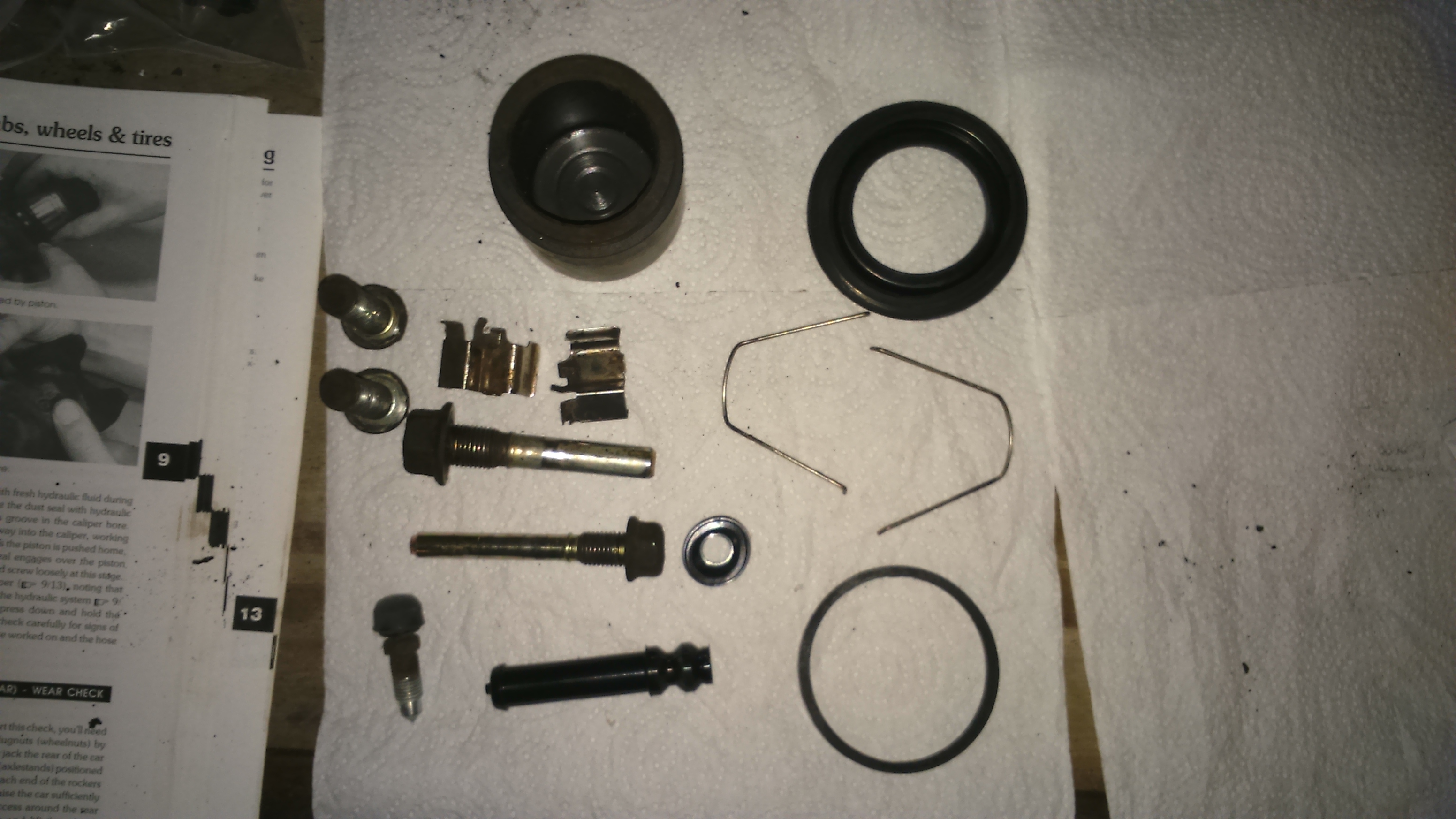
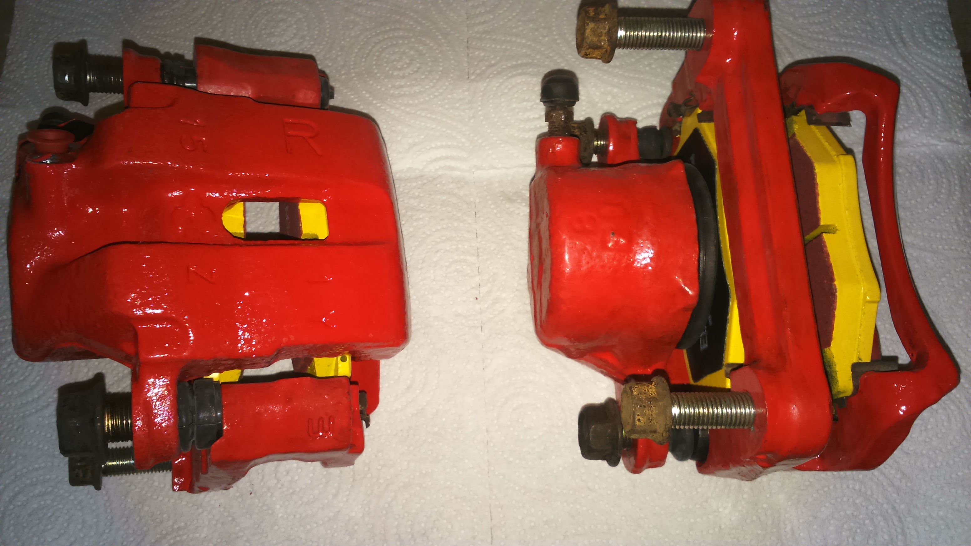
Next job was to manually adjust the rear brake calipers and fit the handbrake but on doing so, I found that one of the rear cables was seized so had to order new ones.

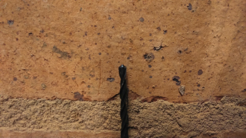
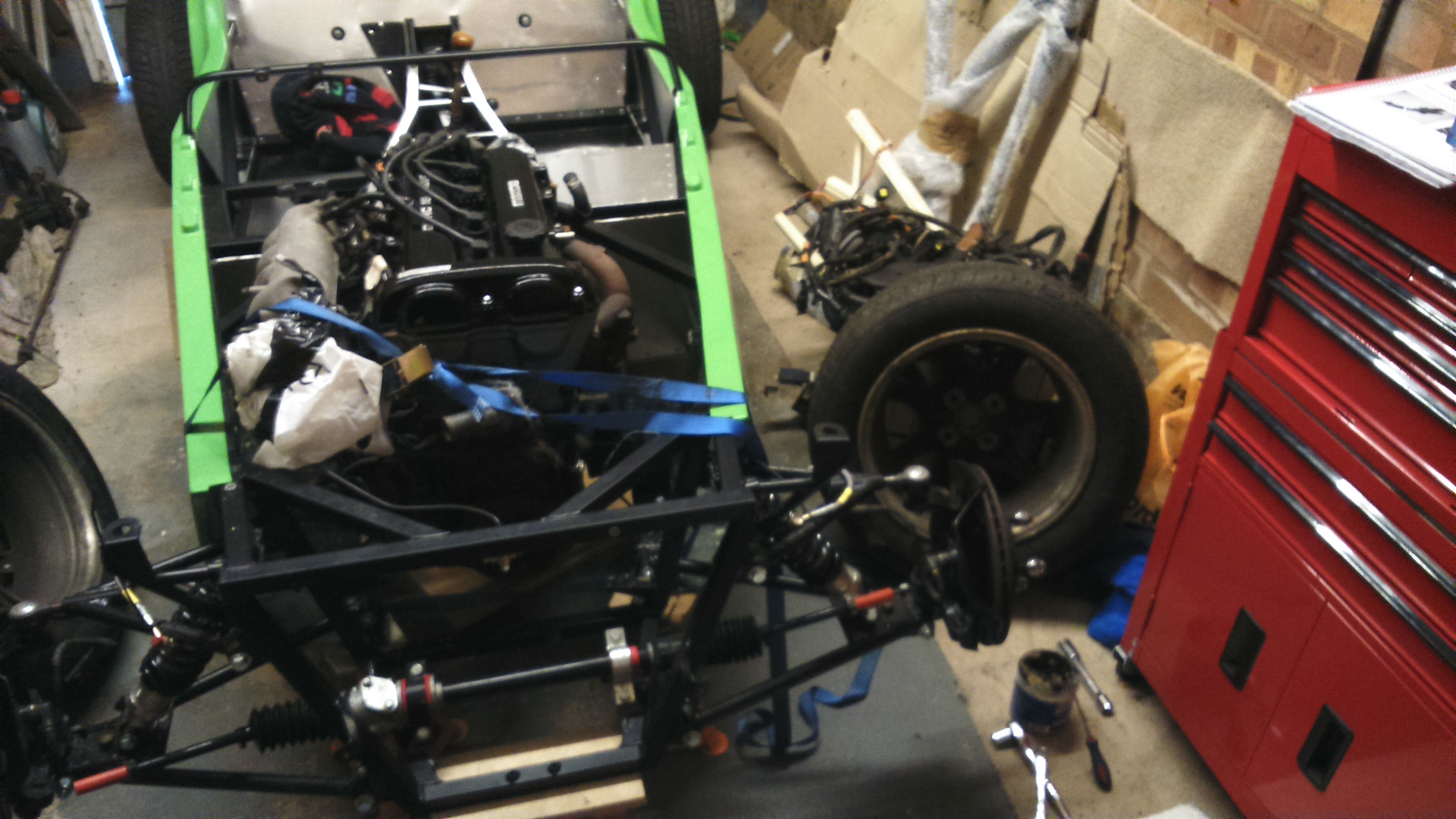
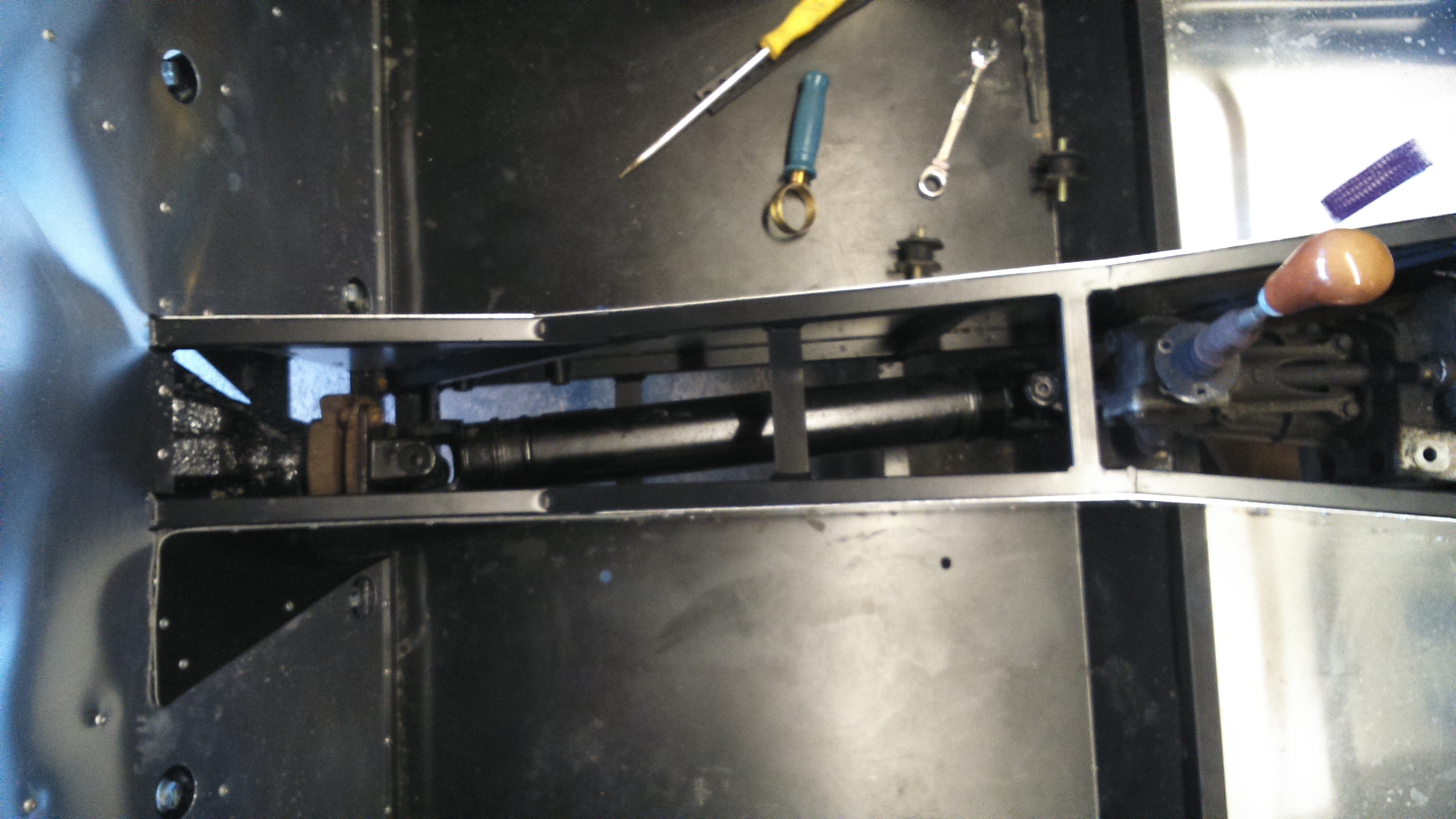
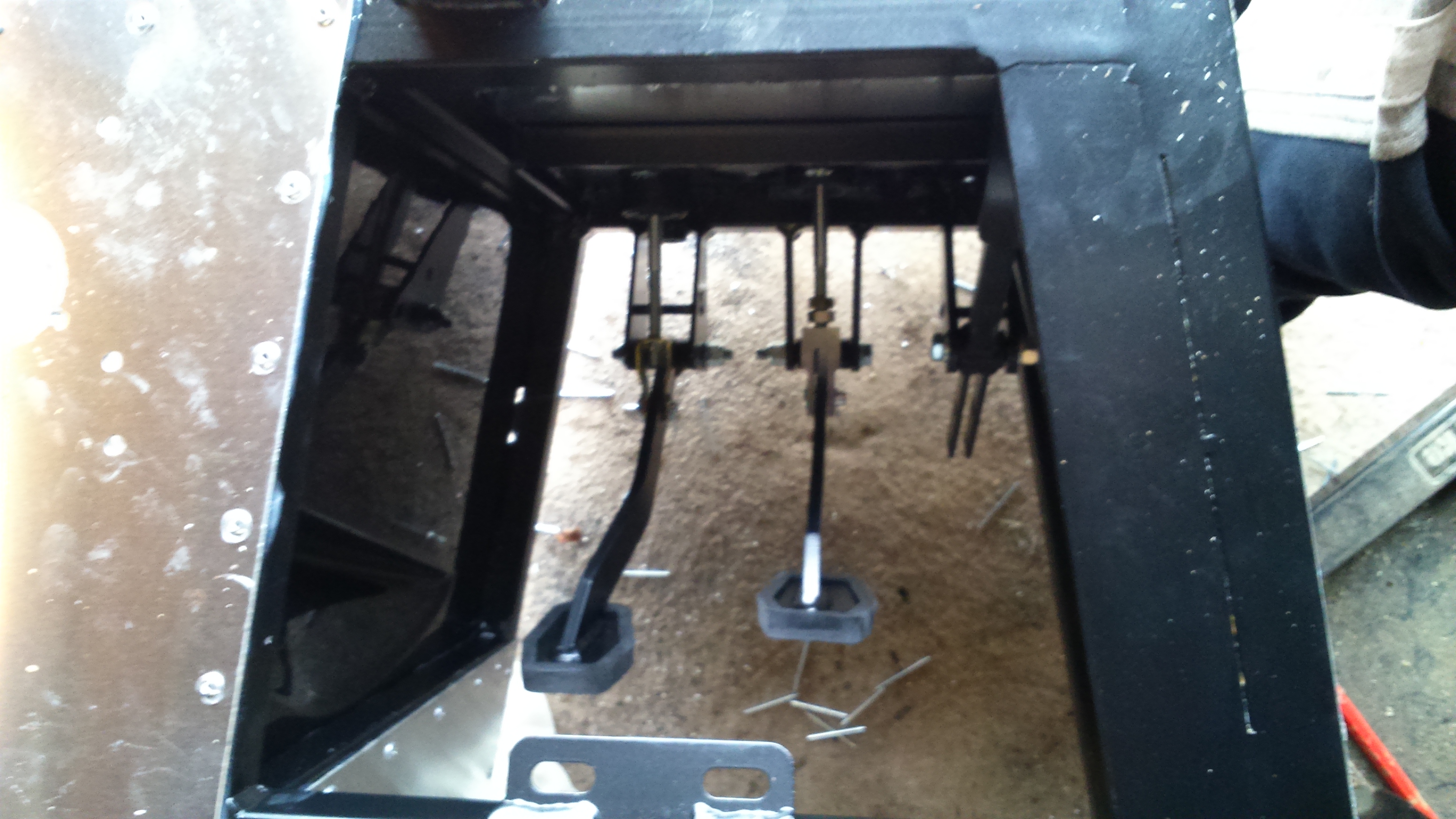
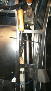
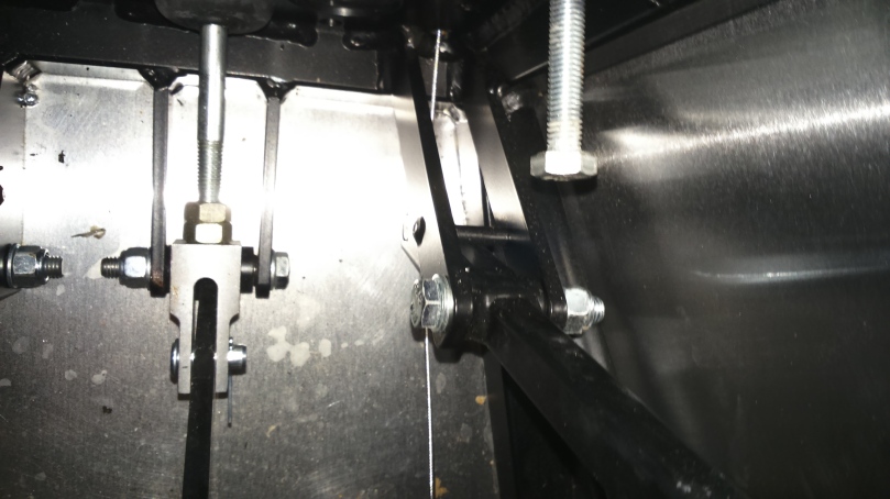
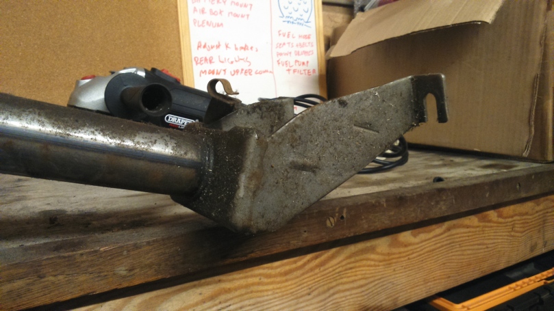
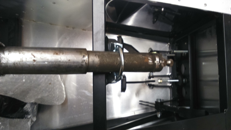
The front handbrake mounting holes were a bit awkward as they had to be drilled blind through the chassis tube behind an aluminium panel and inline with the rear mounting hole that forms part of the chassis, at the same time considering the placement to avoid getting in the way of the gearstick.

Thankfully I managed to position it all correctly and the handbrake works although it could do with a slightly shorter cable.

DSC_1145  DSC_1160  DSC_1166

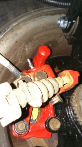
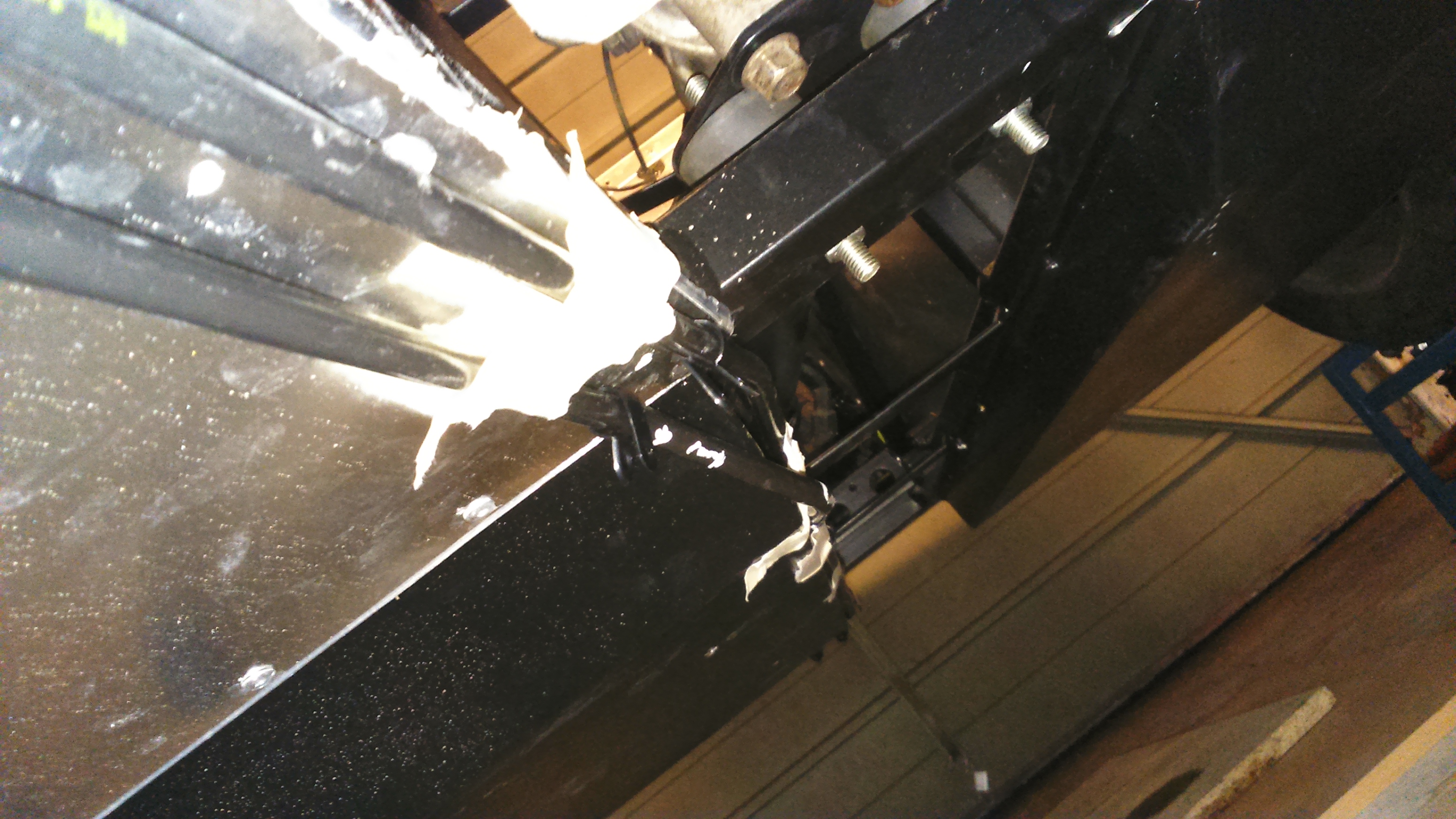
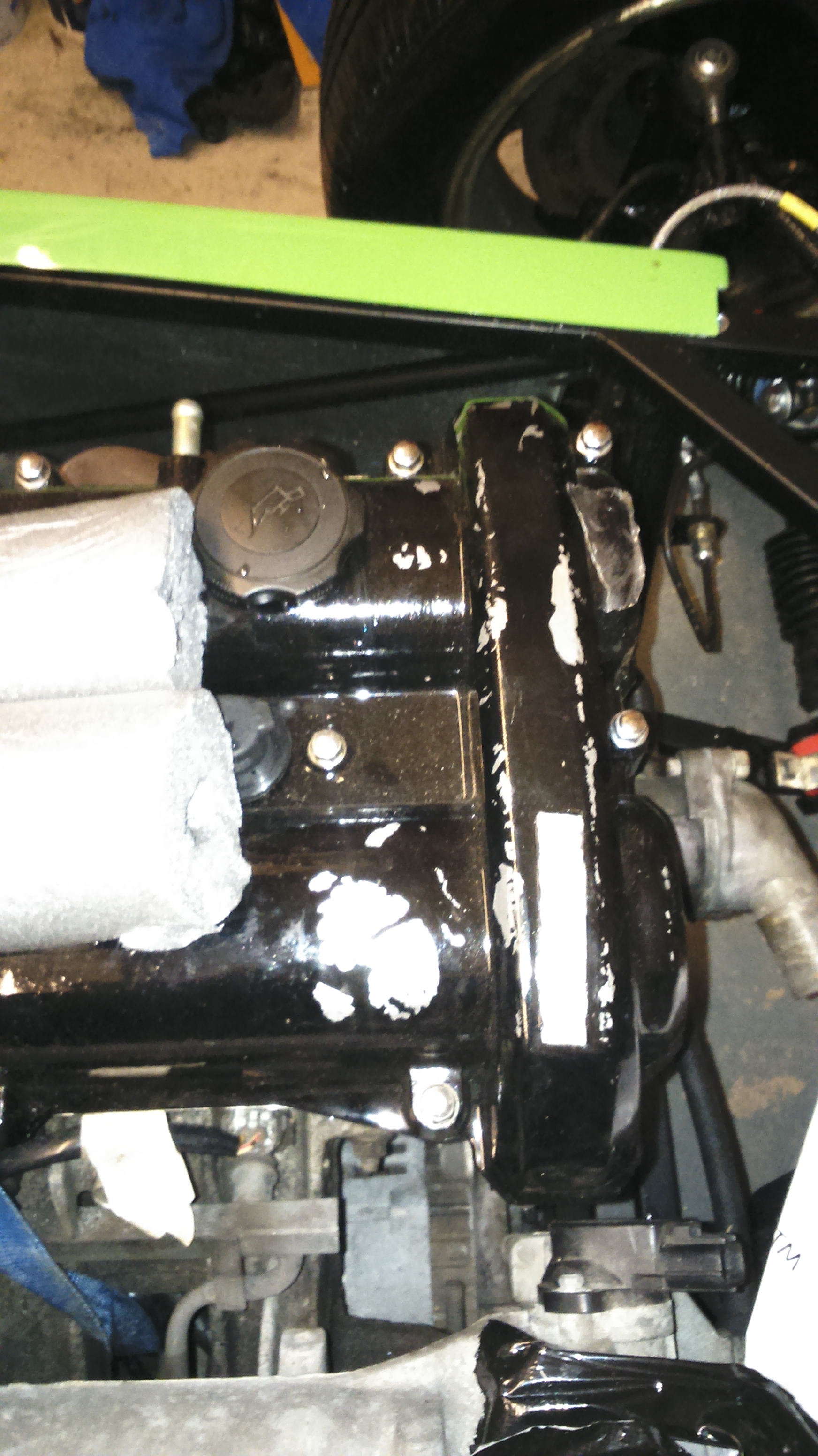
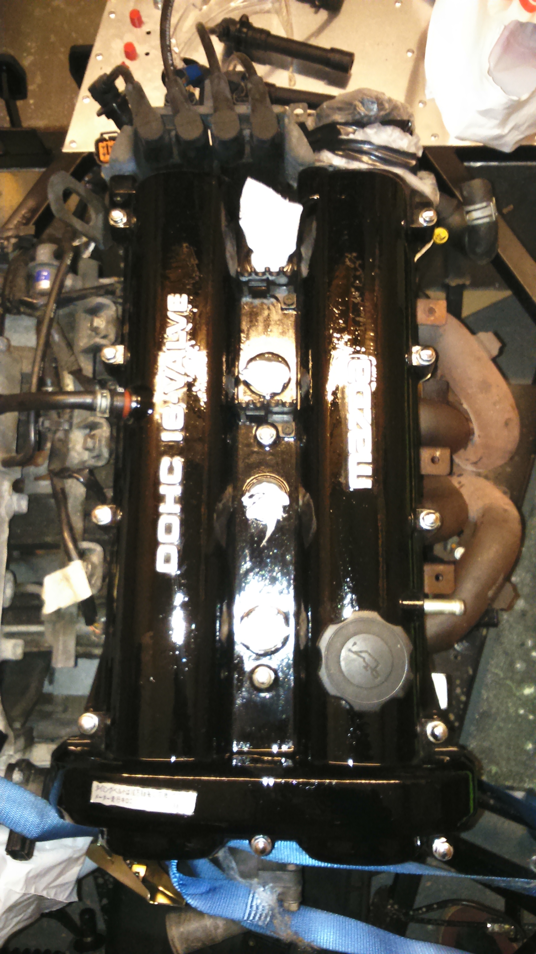
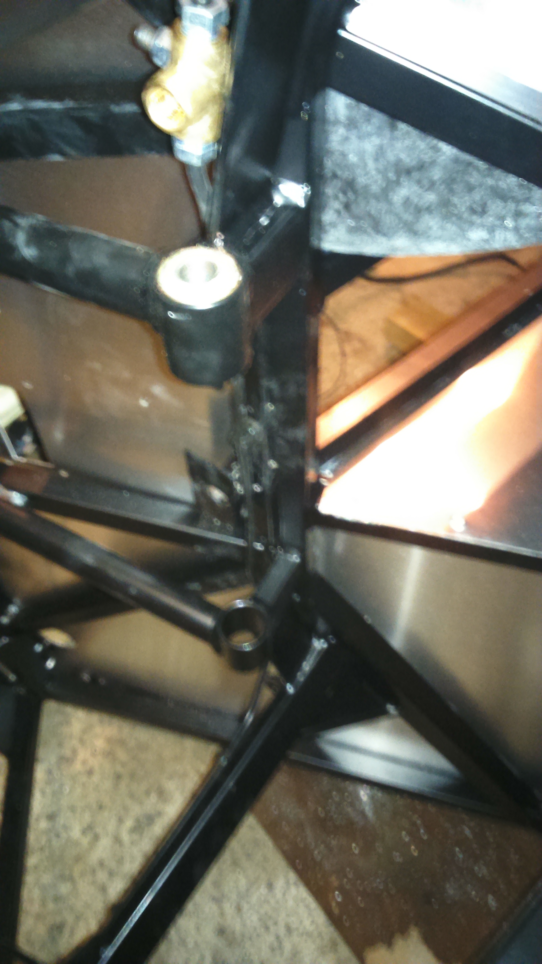
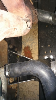
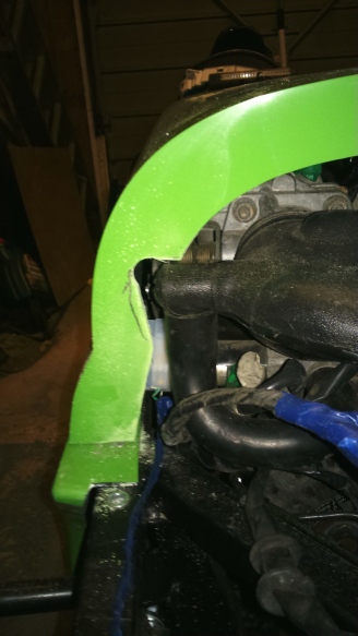
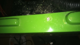
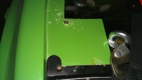
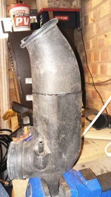
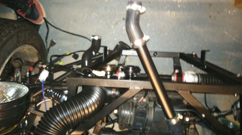
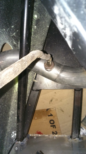
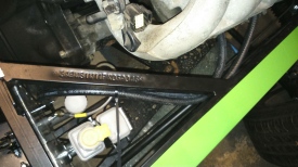
At the weekend, I then got a chance tidy up a few bits such as the plenum and then to start the car, DRIVE IT (about 2m) and let it run for a while which highlighted 2 problems; a slight coolant leak shown below, which was resolved by tightening the jubilee clip and lots of smoke coming off the exhaust manifold.

DSC_1159  DSC_1146

I thought the smoke was only caused by oil on the outside that was used to remove the rusty nuts but I decided to turn it off and buy a fire extinguisher before running it and hoping the oil would burn off.

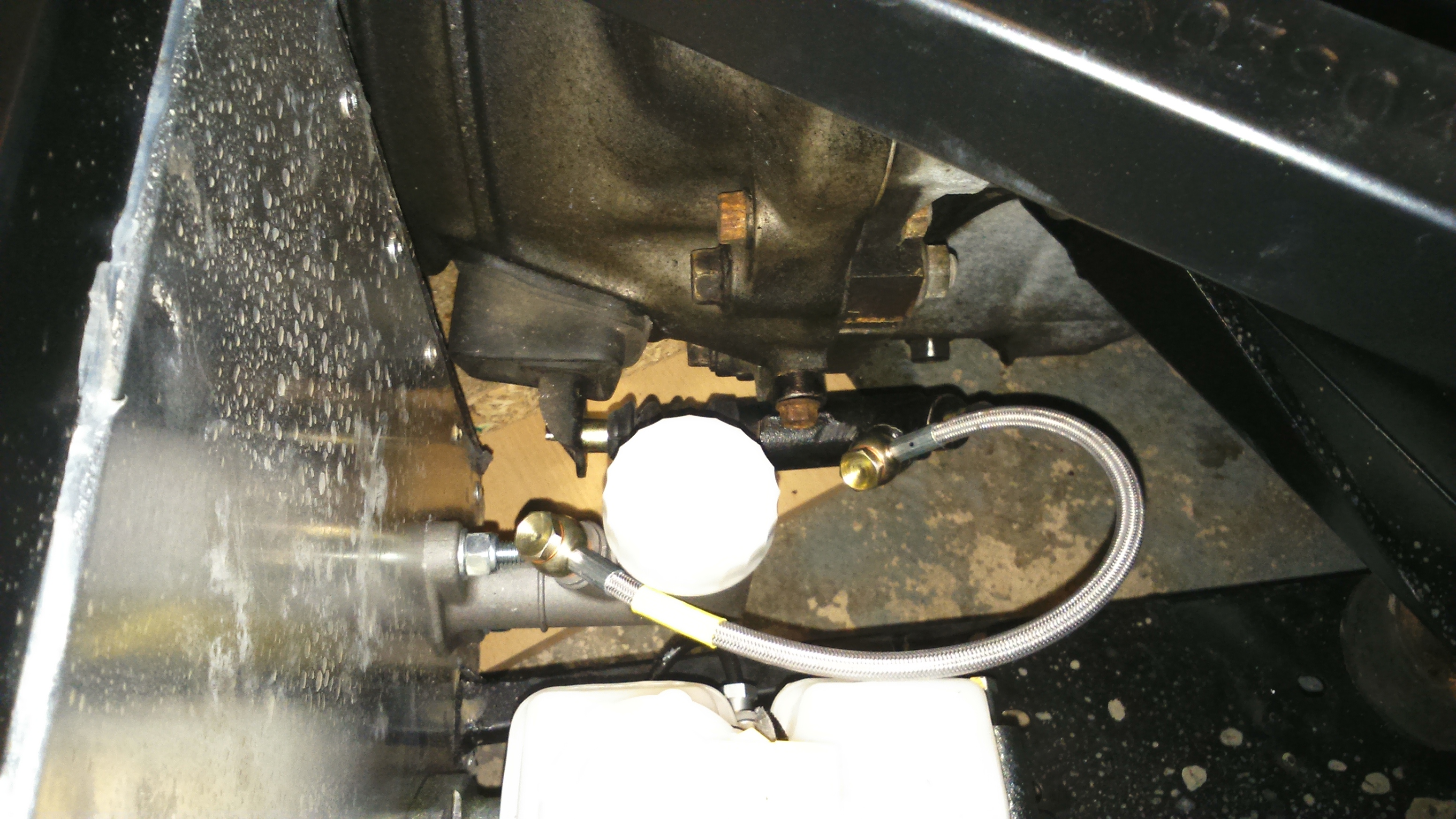
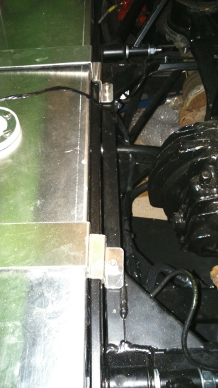
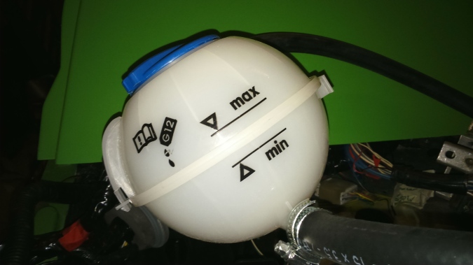
This proved to be correct and the smoke cleared after a couple of minutes and the engine ran well. Checking all the dials, rpm, oil pressure, coolant temperature all worked correctly. The temperature got to about the normal point but before I could test whether the radiator fan would kick in, I found a very small coolant leak from a bolt I had used to blank off a hole in the radiator so turned it off to let it cool down. On the positive side, the radiator leak was at the very top, giving me confidence that the coolant is filled sufficiently.

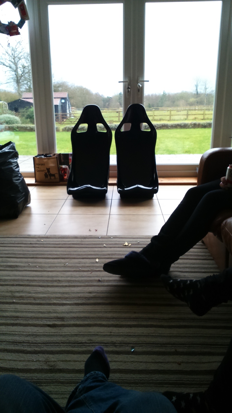
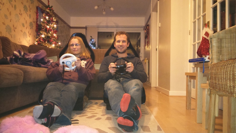
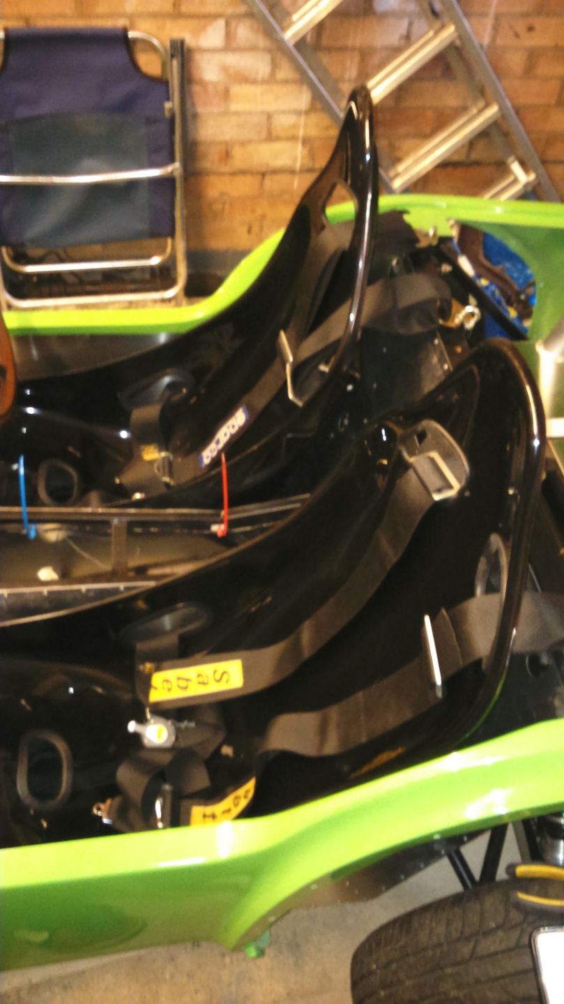
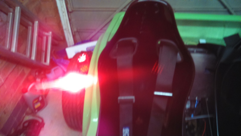
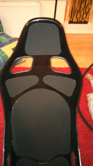
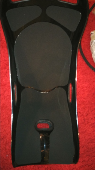
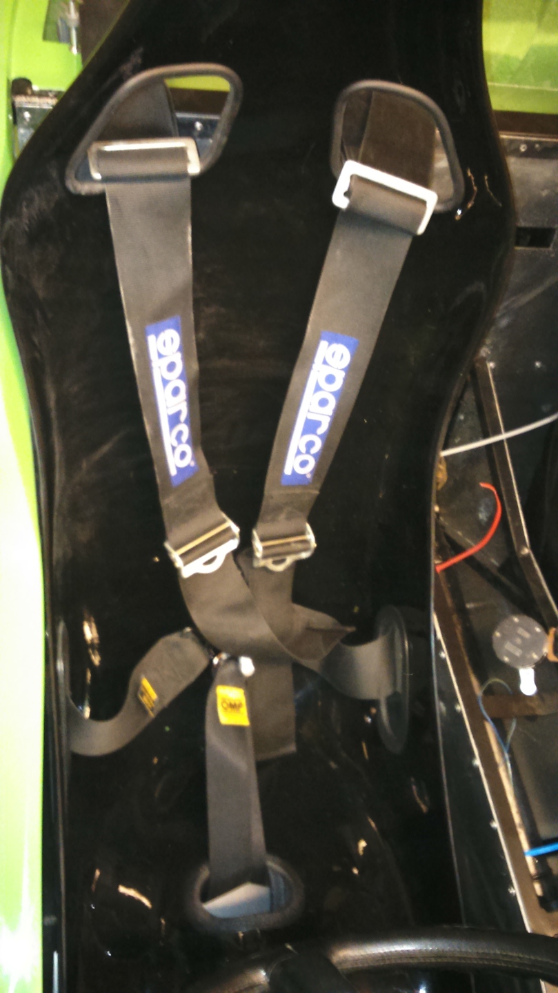
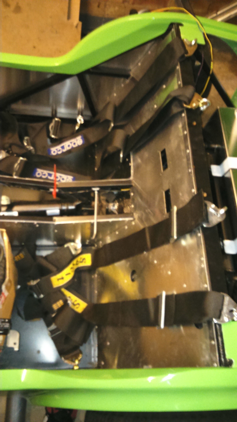
Back inside the warm of the house, I started to create the foam padding for the seats. This was done by designing CAD profiles, printing out on A3, sticking together, checking it fitted the seat and then cutting the 6mm foam around the paper lines.

DSC_1162

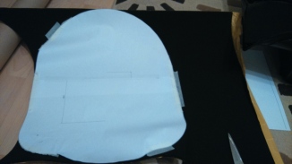
I’m quite happy with the results and the foam has improved the seats that were already surprisingly comfortable. I will stick the foam on the drivers seat at a later date to avoid getting glass fibre dust on it.

DSC_1169  DSC_1170

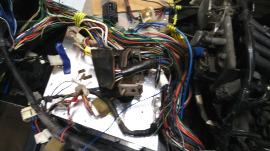
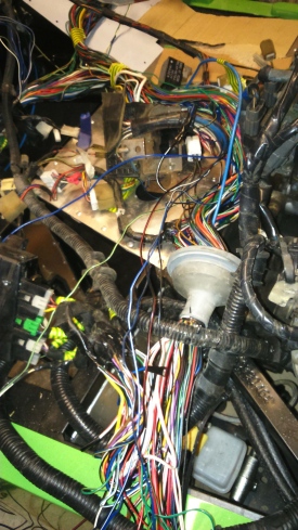
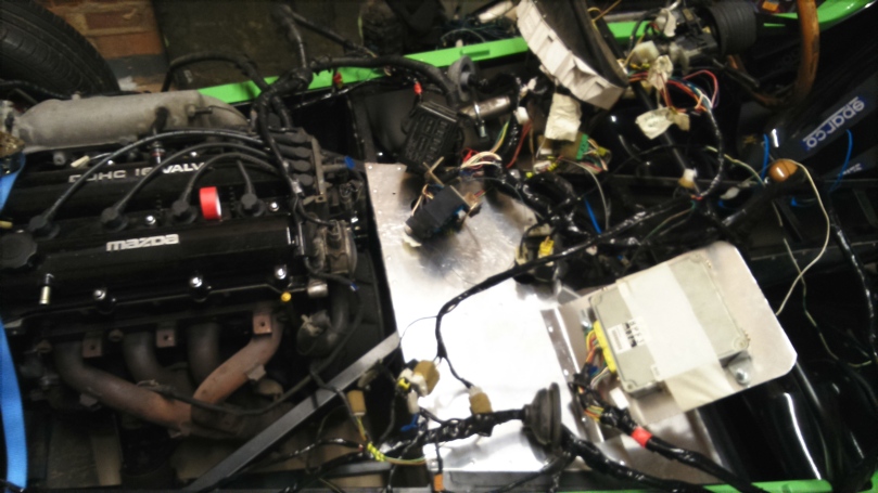
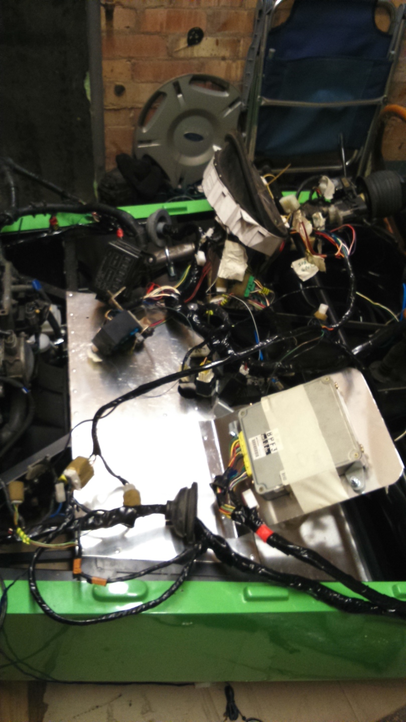
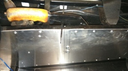
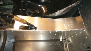
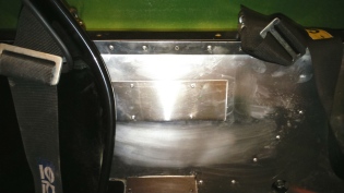
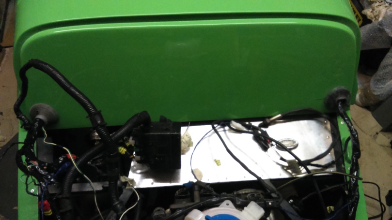
I then spent some time tidying up wiring and put the 2 rear tunnel top panels on with self tapping screws and a blanking plate over the inertia reel seat belt holes.

DSC_1171  DSC_1174

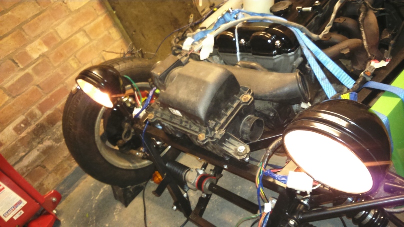
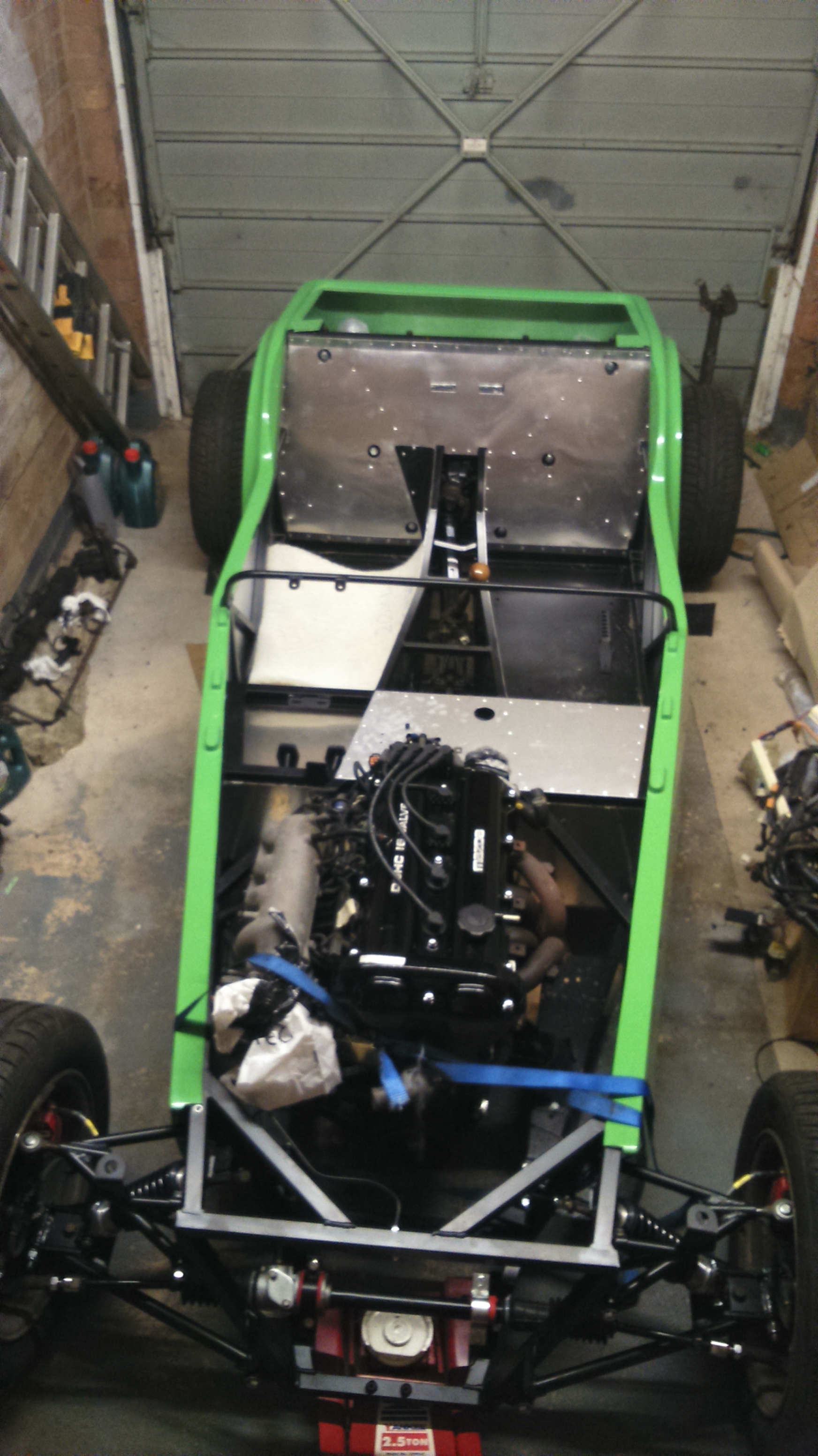
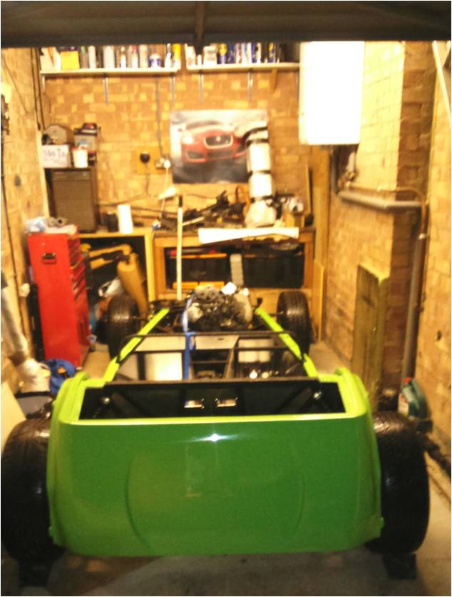
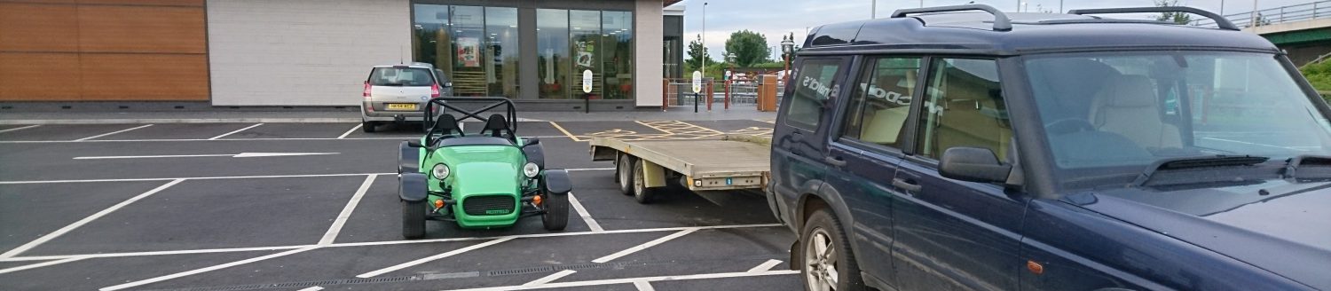
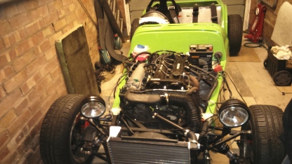
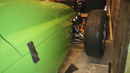
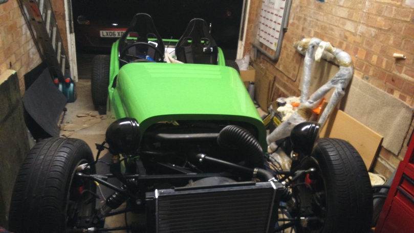
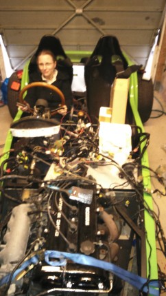
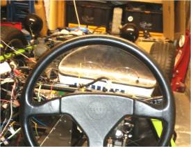
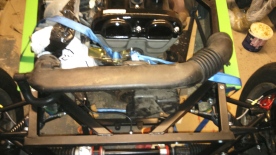
Whilst I wait for other parts to arrive, I started to sort out more of the body. The photo below is with the bonnet and nose cone placed on but not fitting properly!

DSC_1177

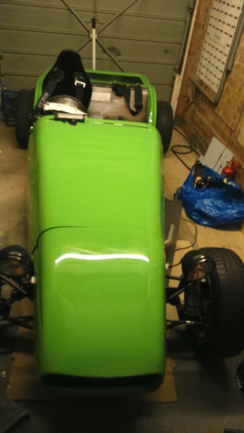
The nose cone and bonnet need to be modified to miss the plenum.

DSC_1178

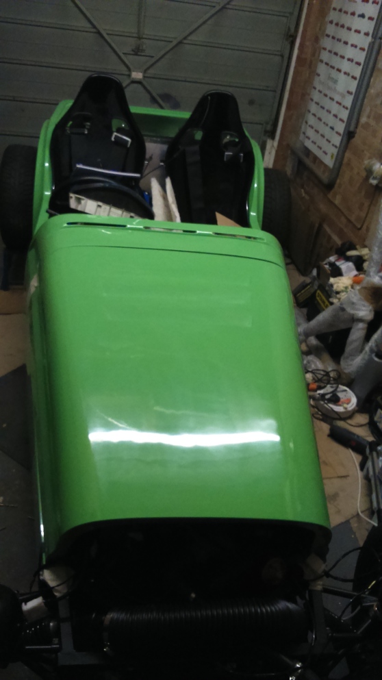
The nose cone and bonnet are then placed on and holes marked in the nose where holes are required to bolt to the chassis. This is incredibly difficult as there is no way to actually see the mounting points when both the nose and bonnet are on. I therefore did it through taking lots of measurements and taping the bonnet and nose together to ensure they stayed aligned.

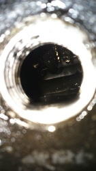
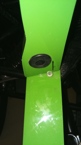
Once the holes are made, the nose cone has grommet put into the hole (black line marks where Westfield say to put the hole but the grommet is too large to go there…

DSC_1185

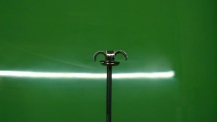
The bonnet then has pins put into the front to joint the nose cone

DSC_1182

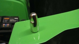
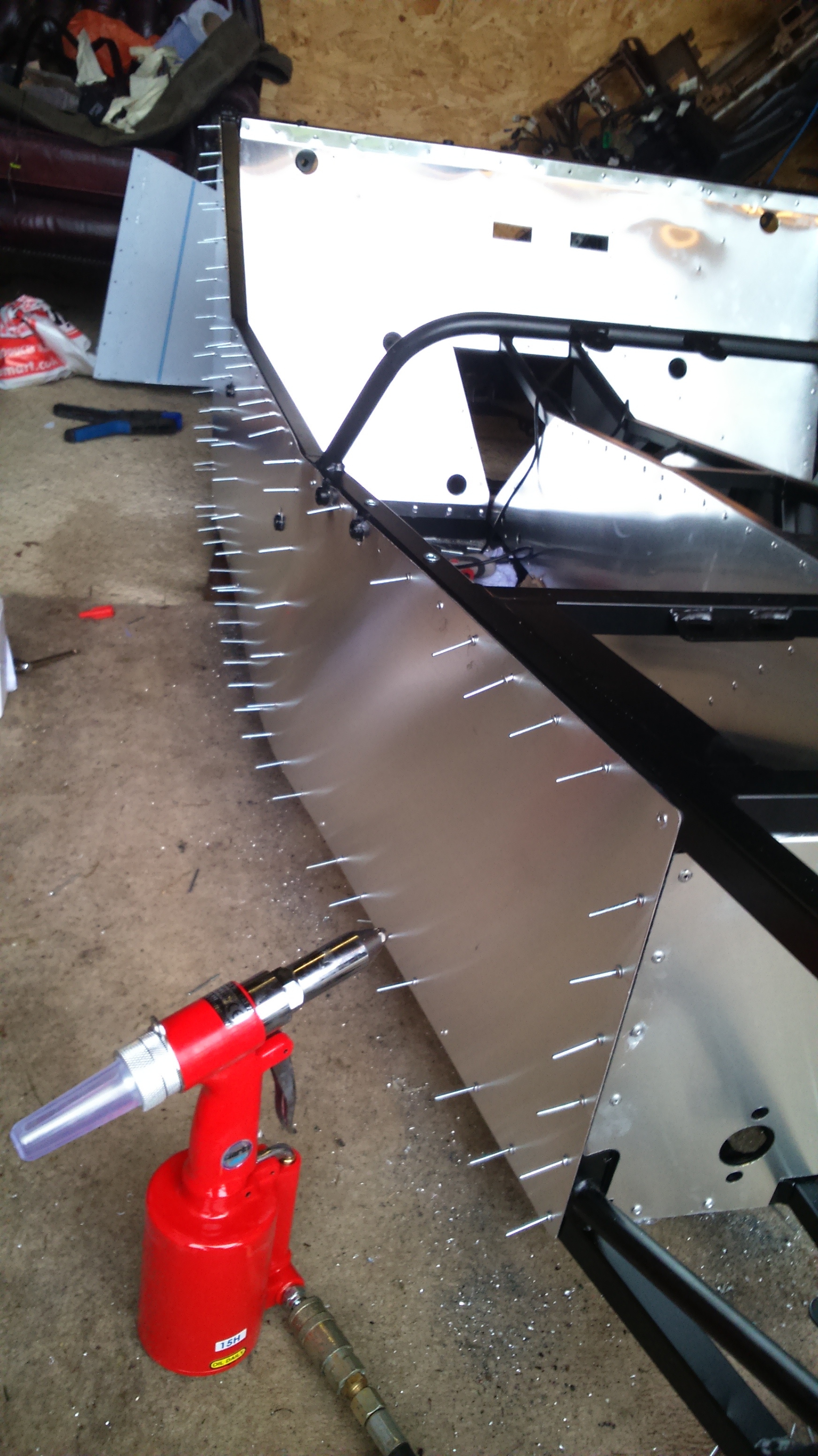
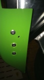
Once this is all in place, the bonnet catches are added at the rear end of the bonnet use peel rivets to hold them to the GRP.

DSC_1189

This is a peel rivet that is used as a normal rivet is more likely to shatter the GRP panels.

DSC_1191

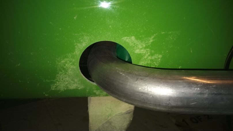
I now have my exhaust silencer and mounting kit so next job is to sort out a pipe to join it to the existing manifold as Westfield don’t have any left.

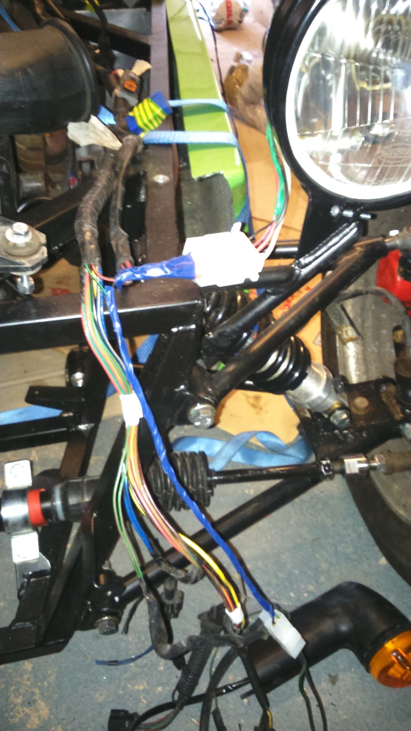
One of the other next major jobs is to fit my new speedo which Westfield estimate will be ready in 1-2 weeks. Then there is lots of tidying up to do, especially the wiring which is open until the speedo is wired in o avoid doing it twice.

It Lives!

In preparation to test start the engine, I had a couple of jobs to finish. I made some lower radiator / fan brackets from the inertia reel seatbelt cover that Westfield provide. It’s only thin plastic but will do for now (as I write this, I have the GRP parts to fit). I then attached with the radiator and fan.

Next was to fill with coolant. This was an awkward process as the expansion tank attaches to virtually the lowest point in the system. I filled through here as much as I could, then removed one end of the top radiator hose and filled through there until coolant started to leak from the other open end. I think there will still be some air to come out but it is mostly full. There was a slight leak from the lower radiator hose. This hose seems to be slightly larger than the others but is fine after making the jubilee clip really tight.

Final job was was to attach a ground wire to the fuel tank to prevent static build up.

I checked everything over carefully and then put 5l of petrol into the tank. I checked the fuel system again and all looked fine.

Everything was ready so I turned the ignition on briefly to build fuel pressure. I checked under the car and found a slight fuel leak so tightened this up and it was time to attempt to start the engine….

(Video doesn’t always seem to appear but is also here: https://www.youtube.com/watch?v=cljqbjU4aws)

It works! I stopped working on the car for the evening at this point before something went wrong!

As I had done this with the body clamped in place, now was the time to rivet it in place using special countersunk and larger body rivets.

DSC_1112DSC_1114DSC_1113

Slowly looking more like a car…

DSC_1108

Next was to drill 2 large holes in the scuttle panel for the wiring plus a slot for the steering column, this was then bolted down to the chassis. This took lots of time to get the holes in the right place and get everything lined up properly.

DSC_1118

Then with the bonnet in place too:

DSC_1119

Doing this made me realise that the intake ducting doesn’t fit with the bodywork in place (without rubbing the brake pipe). Long term I may change to a different filter type and remove this problem but for not, I decided to shorten and glue the plenum which will then give me lots of room. The cross section profile isn’t 100% consistent so there is a bit of a line.

DSC_1122

At this point, I also covered the fuel hose and some of the wiring in convoluted tube to protect it. I will finish the wiring at the front once I know it is all working.

Now I am working towards starting the car again and reversing it onto my drive. Then I will let it run for a few minutes to try and bleed the coolant system, ensure the temperature gauge /sensor works before I replace the gauge and check that the fan kicks in once warm. There are quite a few odd jobs to sort out before then but hopefully it will happen in the next couple of weeks.

Fuel & Cooling systems and Exhaust

First job was to sort out the fuel circuit and get everything connected up.

After needing to order more parts and then damaging the threads on the first fuel tank connector, I connected up all the fuel hoses with filter, pump and tank. I still need to get some convoluted tubes and then fix the hoses in place permanently.

DSC_1067DSC_1079

Fuel tank was then fixed in place after re-bending the tank straps to fit over the IVA crash bar.

DSC_1097

Then connecting up the majority of the coolant system including my new expansion tank. I bought a VW header tank, normally used for all VWs up to 2l as it is a simple shape and will be easy to mount at 1/3 the cost that Westfield charge for an expansion tank.

I still need to attach the radiator to the car and then attach the hoses but need to make some brackets first.

DSC_1072


DSC_1073

DSC_1098

Next job was the scariest so far, drilling a hole in the main part of the body work for the exhaust to pass through. I went for a slightly larger hole cutter to give me a bit of tolerance but it lines up fairly well (link pipe is loose fitted below).

DSC_1081

I also had to drill a hole in the exhaust link pipe for mounting the lambda sensor. I bought a small threaded insert that fits nicely into the 22mm hole I have drilled below.

DSC_1085

Next was the fuel filler flap and hose. The first step was to locate and drill another large hole in the main part of the body, luckily this went OK again.

DSC_1083

Then drill the 6 mounting holes for the fuel flap.

DSC_1087

For IVA, the fuel filler flap has to be tethered to the car, as shown below, done with some picture hanging wire and a crimp connector on the back of the cap.

DSC_1088DSC_1090DSC_1089


I need to recheck everything is tight but that is the fuel system complete and I even went out and bought 5l of petrol ready to fill.

The electric and fuel systems are now complete (electrics will need modifying for my new speedo when it arrives), the exhaust is sufficiently complete to (loudly) test start the engine before adding the silencer. The remaining jobs before I can attempt to start are to make radiator brackets, attach a ground wire to the fuel tank, check everything is tight, fill coolant and fill with petrol.

I have designed some radiator brackets which are being cut from GRP so in the meantime, I got on and properly mounted the driver’s seat with harness approximately adjusted. The 4 lower belts need the seat out to get enough room to adjust them.

DSC_1093


The Rest of My Christmas Progress

In the remainder of the holiday I managed to get a few more tasks done.

After the problems I had with the clutch hydraulics, I was dreading filling the brakes but with help from my assistant it went OK and the brakes now work.

DSC_1049

Attached the Westfield throttle cable through the pedal. The pedals need adjusting so I will do that before I cut down the throttle cable.

DSC_1051

And changing the steering wheel for an IVA friendly one (Old Nardi wheel on the left image below, Momo wheel on the right with crash pad covering the centre of the wheel as required for IVA). Both are a bit big and make it harder to get in the car than it should be.

Getting the old wheel off the column was a challenge. In the end, I removed the wheel from the boss, including 1 screw with a rounded head (and found that the 2 wheels used different bosses), then removed the old boss with a rubber mallet.

Wood steering wheelMomo Steering Wheels


Christmas Progress

On the first day of the Christmas holiday, I wanted to get a few odd jobs done before moving on to the wiring.

First was the upper steering column which needs to have this bracket cut off with an angle grinder.

DSC_0978

Once cut off, the column could then be fitted to the car. (The U clamp is too big in this photo but is now correct)

DSC_0982

Next I fitted the fuel hoses between the pipes and the fuel rail and then the intake plenum.

DSC_0979  DSC_0983

I’m not sure if I got the wrong bolts in my kit or used the wrong ones elsewhere but the rear upper wishbone bolts were not long enough so I replaced these with new ones and torqued up all bolts in the suspension.

I then put the fuel tank in place with foam padding around the straps and chassis surface.

DSC_0987

Next were the harnesses which were a donation that had been used for racing but were now out of date (Thanks Tom!). They will need adjusting but I will get the seats and crutch belts in first.

DSC_0990

Then it was time to sit in and pretend to have a drive! When sitting on the floor I actually look through the steering wheel rather than over it.

DSC_0986

Now it was time for the wiring. I started with the lights in the hope I could get at least something working by the end of the Christmas holiday. The headlight units have 4 wires attached (dipped beam and main beam) but nothing for the sidelights.

I had bought a load of connectors for the lights and crimped and soldered the terminals on.

DSC_0996

After struggling to open the lights up, the side light connections were obvious and had no wires attached at all so I attached my own with crimps.

DSC_0999

I then laid out the wiring harness from the MX5 and attached what I could.

DSC_1004
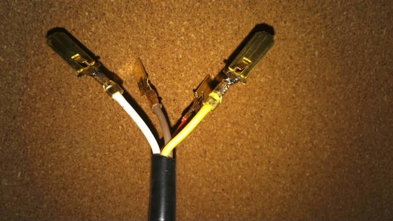
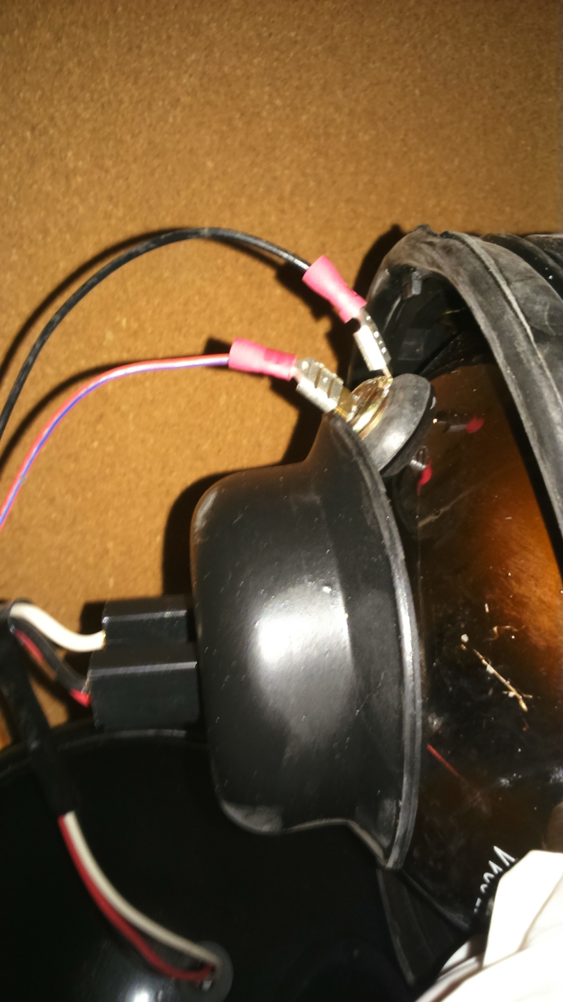
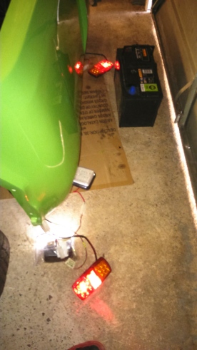
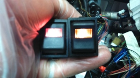
I repeated a similar  process for the rear lights too, using the wiring that I had previously attached.

I then connected a battery to test the lights and IT WORKS! Well, the sidelights, dipped beams, full beams and number plate light worked. There is virtually no circuit for the fog light yet (as my car was an Eunos and the added circuit was removed). The reverse light worked but the wiring didn’t reach the gearbox wiring. The indicators flashed but very quickly indicating an error and the hazard lights didn’t work as I left the switch and wiring in Norfolk…

DSC_1005DSC_1006DSC_1007

From some research, it turned out that the indicators were flashing too fast as I have used LED indicators for the rear and side repeaters. The flasher unit therefore doesn’t see enough current and thinks there is a problem.

From further research, I initially found 2 solutions; Add some big resistors to each circuit to draw more power (this seems a bit of a bodge and the resistors will get hot if used much), or get a different flasher unit. The flasher units have either 3 or 4 terminals so I checked how many mine had which turned out to the 7…

So I carried on my research and found an American Miata forum where they modified the Mazda flasher unit to achieve the desired result by replacing resistor R1 in the RC circuit. At the top of the photo below is the resistor I changed to a 1 mega ohm 1/4W resistor. This isn’t in very neatly as the heat damaged the bottom of the board slightly so I stopped (the connection is fine)

http://forum.miata.net/vb/showthread.php?t=335534

DSC_1009

With this back in the car, the indicators flashed perfectly and it cost me nothing!

Then I spent a few days away for Christmas and progress stopped but I did get some seats from my parents (Birthday and Christmas present). These are made by JK Composites out of GRP and weigh about 4.5kg each with the base.

The version I went for is N3946 as this is the widest that will fit in the passenger side of my car. These are about the right size for me but there may be limitations on who can have a lift!

I’m very impressed with these seats so far and are surprisingly comfortable without any padding.

DSC_1027

They are also great for playing Mario Kart…

DSC_1028

And then placed in the car. I need to either get some tracks or drill further holes in the chassis to mount them properly. For now they are held in with 2 screws so I can sit in without them moving.

DSC_1029

Next was to remove the wiring that isn’t needed and save some weight. This is a very slow process as I won’t be needing electric mirrors, electric windows, heated rear screen, audio…

There were also a lot of wires that needed either lengthening or shortening so this took up even more time.

There were times that I wondered what I had done and if it would ever work again:

DSC_1031DSC_1032

I then tested that everything still work and even tried the starter which successfully turned the engine over!

Once mostly sorted out, I started insulating the wires. I will be replacing the speedo which may result in more simplification.

DSC_1036DSC_1037

Once the wiring was relatively tidy, I sorted out the switches for the hazard lights and fog light, plus the relay needed for the fog light (it can only come on when the lights are on and when ignition is on.). I therefore have side light power running through the switch which controls the relay and then power through the relay which goes to the fog light. The source I found for this was the electric window fuse as I probably won’t be needing that anymore.

The blurry images below show that my circuits worked and the switches are lit when the side lights are on.

DSC_1044  DSC_1041

DSC_1039

Brake Pipes, Fuel Pipes and Wiring

Progress has been a bit slower recently but I have got a few things done and have been preparing for a few days on the car around Christmas.

The first job was to drill and rivet all the clips for the brake and fuel pipes running under the car. The fuel pipes were relatively easy as the exact end position is less critical (they will mount to rubber hose). The brake pipe was a bit more difficult as I had slightly more pipe than needed at the rear and had to shape it carefully to avoid getting near the diff.

I used an air powered grinder and small drill bit to make pilot holes and then a normal drill to finish the holes. During the procedure, I must have found a hardened part of the chassis near a weld and melted the end of a drill bit…

DSC_0925

Whilst the car is in the air I drained and filled the gearbox oil. It was a bit hard to access the fill hole so used an oil can with a hand pump in it. The only way to see the level was to use my phone and take a photo in the fill hole.

DSC_0932

The next task was to do the rear harness. This involved taking the Mazda harness, removing insulation, cutting off the un-needed parts, cutting down the bits that are needed and then making a couple of additions for number plate light etc. My car was an Eunos so I also had to add a fog light wire.

I ordered my lights and as soon as they arrived, I fitted the headlights which took 2 minutes and looked like progress!

DSC_0958


Brakes, Suspension, Steering, Clutch, Fuel Pipes and the Remaining Brake Pipe

The next step was to reassemble the brakes, attach them to the car and correct a couple of things with the suspension/steering whilst doing so.

I started with the front calipers. One of the old calipers had seized so I only had to rebuild one of them. I initially struggled with getting the longer seals through the caliper bracket but a tiny bit of WD40 and the slid straight in.

DSC_0866 DSC_0869

Once done, I jacked the front of the car up and fitted the calipers. Whilst doing so, I copper greased the joints that I didn’t do during the initial part of the build and torqued up the joints that don’t use the metalastic bushes.

Whilst apart, I tapped the M14x1.5 thread in one of the upper front wishbones which had a little powder coating in it. The ball joint then went in perfectly.

DSC_0872 DSC_0874 DSC_0877

Whilst the front was in the air, I also decided to fit the track rod ends. I removed these from the Mazda steering rack (that I luckily hadn’t had time to get rid of) and fitted new boots using a 32mm socket and G clamp. I fitted these with the extenders, set the toe about level and dropped the front back down.

DSC_0890DSC_0879DSC_0899

One evening that week, I then decided to fill and bleed the clutch system. Unfortunately I just couldn’t stop it from leaking at the slave cylinder end. I found a few problems that caused this; the standard Westfield banjo bolt is too long and the aftermarket slave cylinder does not have a flat surface to seal against the copper crush washer (this wouldn’t be a problem in the Mazda as the hydraulic pipe has a different fitting). In trying to get this to seal, I then tightened it too much and broke the thread in the cheap slave cylinder…

I therefore ordered a Mazda slave cylinder and a shorter banjo bolt (http://www.carbuildersolutions.com/uk/banjo-bolt-m10-x-1). Once these arrived I fitted them and it worked perfectly straight away.

DSC_0889

Next I rebuilt and fitted the rear brake calipers and  put on the car. I also rebuilt part of the rear suspension and think that some of the bolts for the upper wishbone are too short so I will order some 4 1/2 inch bolts. I think I may have used the wrong ones elsewhere. The manual says to use 2 1/2″ bolts for the upper rear wishbones but on the Mazda SDV they need to hold the diff bracket so need to be over 4″.

DSC_0902

Slightly out of sequence, next I bent the feed and return fuel pipes and taped these in place under the car. I think I read somewhere about  not needing the carbon cannister so will investigate that before bothering to bend the pipe for it. These were much easier than the brake pipes as the end points aren’t so defined and the profile is generally flatter.

DSC_0908 DSC_0909DSC_0912

I then bent the remaining brake pipe (master cylinder to rear T piece) and taped to the car. I started at the front and actually had a bit too much pipe when I got to the T piece so would have been better off starting at the rear.

DSC_0916

Next job is to drill the holes and rivet all those P clips in place!

DSC_0897

The Return to Warwickshire

A few days after getting the engine in, my Dad winched the Westfield onto a trailer and brought it back to Warwickshire for me to continue the build.

After struggling to push it back onto the drive (due to the front wheels not being connected to the steering rack!), we put the main part of the body on the chassis for storage.

Westfield return

The first job was to put the propshaft into place now that it had been shortened by Bailey Morris. Once this was in, at the gearbox end, there was about 20-30mm of the splined section outside of the gearbox and judging by the corrosion, only about 10mm of this had been exposed when in the Mazda. I don’t know if this would have been a problem but decided to move the engine back a little whilst it was relatively easy to do so.

The slot on the right hand engine mount was almost still OK ( I enlarged it by about 2mm) but it meant re-drilling the holes on the left engine mount and for the gearbox mount. Without the engine hoist to remove the engine, the gearbox mount meant drilling the holes from underneath the car, then sliding the engine backwards before locating the mounts. I also used this chance to fit the gearbox mounts recommended on the WSCC forum here.

With this done and everything bolted in place, I put the propshaft in place and the splined section was now very close to where it had been on the Mazda so I’m happy.

DSC_0856

I have now created a list of jobs and started to work through them:

During transport, the engine had been protected by the combination of a canvas bag and sticky back plastic wrapped around, this had definitely worked to keep the worst of the rain off the engine but unfortunately took some of the paint off the cam cover so one of the first jobs was to repaint this.

DSC_0853    DSC_0858

Fitting the clutch slave cylinder and hose. The master and slave cylinders are very close so I can’t work out a better way to route the hose. Need to get some fluid and bleed the this.

DSC_0863

New air filter into the standard box, tried to mount it to the chassis but I appear to be missing the small L shaped bracket, it’s fairly simple so I will cut one out of some spare aluminium sheet.

DSC_0854

Suspension and Engine Assembly

The next 2 days were spent assembling the suspension and then putting the engine and gearbox into the car.

The chassis was put flat onto the ground and then lifted onto axle stands so that I could fit the suspension. We inserted the bushings at a local garage who let us borrow their press so thanks to Wayne at Greenfields Service Station. These were assembled to the chassis using the supplied bolts.

The diff had to go in before the rear uprights/driveshafts and this was not so straightforward. There is a reduction sleeve that has to go through the diff, unfortunately there are already 2 other sleeves in the hole! These sleeves were forced out and the Westfield sleeve was pressed in.

After lifting the diff into the chassis and trying to bolt in place, we found that the lower diff bracket clashed with the chassis and would not allow it to move into place. The diff therefore came out and I used a grinder and file to take away part of the bracket. The diff then went in and was bolted in place.

The rear uprights were next along with the rear shocks and were fairly straightforward. Westfield had advised shocks with rose joints rather than bushes as the rear shocks are at a bit of an angle, so I ordered a set of Protech Shocks with rose joints and they supplied the relevant spacers to fit this.

The front uprights went on easily although one of the upper ball joints was stiff into the wishbone. The instructions say this is an M18 thread but it is actually M14 so an M14 tap will be needed to clean this thread.

The steering rack was then fitted using the supplied mounts. We found a problem at this stage as one of the track rod ends did not fit onto the rack extensions and would literally just fall off. After a few phone calls with Westfield, they advised that they don’t do track rod ends for the Mazda so I needed to return them and use the standard track rod ends. If I knew that, I wouldn’t have removed them from the uprights with force and therefore destroy the dust boots. Better order some more…

The wheels were then fitted and the car was lifted off the axle stands. This felt like a big milestone and quite an achievement!

DSC_0839

DSC_0840

On my final day in Norfolk, we reattached the gearbox to the engine, attached the various Westfield mounts and then went to attach the rubber engine and gearbox mounts which we did not have… A phone call to Westfield and it turns out we were meant to order these separately. My Dad managed to source engine and gearbox mounts to use. The engine mounts are from a Ford and look exactly the same as the Westfield one although not sure how stiff they are in comparison.

We then inserted the engine and gearbox into the chassis and found that the engine mounts were a long way off lining up with the holes in the chassis. We played around with this for a while but there was no way it was going to fit and even if it had done, the engine would have been at a very extreme angle in the chassis. We therefore fitted the right hand engine mount and re-drilled the holes for the left hand mount. This way round gave enough clearance for the clutch slave cylinder to operate but using the standard holes on the left did not. Once in place, we marked the gearbox mounts, lifted the engine out and drilled the gearbox mounts before refitting.

If the mounts and holes had all lined up then the whole engine fitting could have been done in 30 mins, the large engine bay made this quite easy.

DSC_0848

DSC_0845

DSC_0844

Assembly Starts

The day after the Westfield kit arrived at my house, my Dad collected it along with the engine and transported it to their house in Norfolk which is where the build would start. I had booked a few days off work (which I kept having to change) and would spend these starting the build.

DSC_0818

On 22nd October I drove over to Norfolk via Bailey Morris in St Neots who would shorten my prop shaft.

The first job after arriving and unpacking was to get on with the panelling. The process for this is to clamp the panel in place, drill through the holes into the chassis, de-burr the holes, remove the protection on the panels and then rivet in place.

After a few minutes of trying to find the floor panels in the instruction (that were already welded in), I got on with the first panels round the tunnel. The process was initially very slow using a cordless drill which struggled for power and would take at least a minute for each hole. A change to a mains powered drill and with a sharp drill bit, each hole took about 10 seconds, which got longer as each drill bit became blunt. The air powered riveter I bought was brilliant and saved a massive amount of time, definitely worth the money!

DSC_0821 DSC_0822

By the end of the day, I had the majority of panels in place as shown in the blurry and dark photo below.

DSC_0824

The second day started with more panelling but seemed to go quicker now I had the hang of it. The chassis was turned onto it’s side to do the front floor panels.

DSC_0825 DSC_0830

I put the pedals in before the chassis was turned onto it’s side. This didn’t take long and it felt nice to be assembling parts.

DSC_0828

Whilst the chassis was on it’s side, I did some of the brake pipes. The pipes that go into the master cylinder require bends very close to their ends which can’t be done with the pipe bending tool I bought. I therefore left these off while I work out how to do this neatly. The best plan I can find so far is to put wire in the pipe and then bend by hand, the wire should stop the pipe collapsing. I need to get some less blurry photos but this shows the rear pipes where they separate from the T piece.

DSC_0835